Finger guided suture fixation system

a suture fixation system and finger-guided technology, applied in the field of suture fixation system, can solve the problems of preventing visualization of the target location and challenging delivery of surgical instruments to the target location

Active Publication Date: 2013-06-18
COLOPLAST AS
View PDF53 Cites 2 Cited by
  • Summary
  • Abstract
  • Description
  • Claims
  • Application Information

AI Technical Summary

Benefits of technology

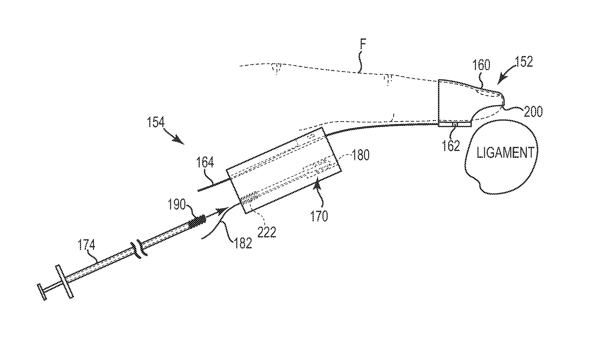
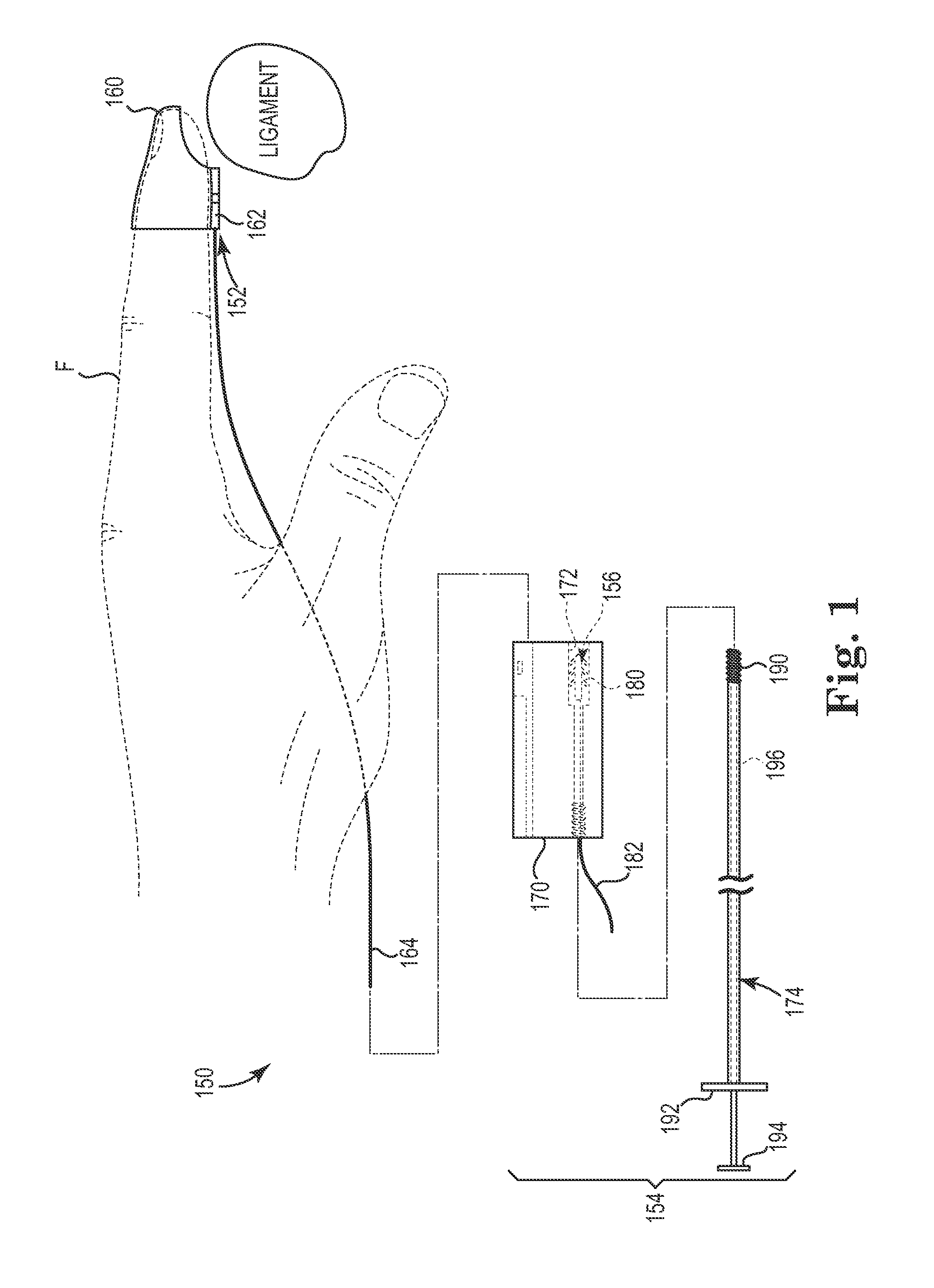
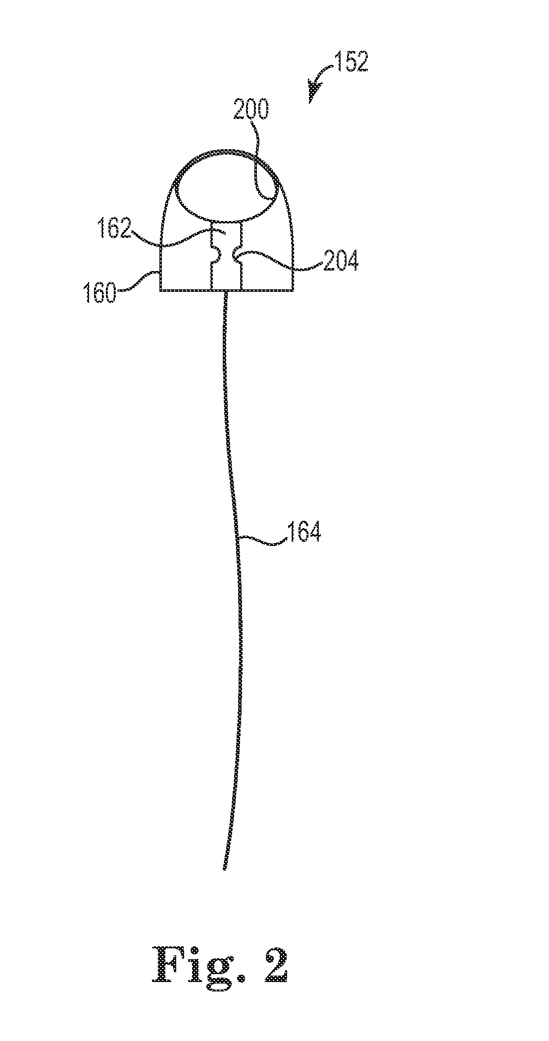
[0002]One aspect provides a suture fixation system including a suture assembly having an anchor, an introducer, and a delivery device. The introducer is attachable to a finger of a person and includes a platform attached to an exterior of the introducer and a zip line attached to the platform. The delivery device is movable along the zip line and configured to removably retain the anchor. The introducer allows the finger to identify a target landmark within a patient and the delivery device positions the anchor for insertion to the target landmark.

Problems solved by technology

Intracorporeal suturing of tissue during surgery presents challenges to the surgeon in that the surgeon is called upon to manipulate one or more suturing instruments within the confines of an incision formed in the patient's body.
However, the target location is often disposed inside the patient's body at an angle that is difficult to reach and can have a depth that precludes visualization of the target location.
Delivering surgical instruments to the target location is challenging when the target location cannot be visualized by the surgeon.

Method used


Image

  • Finger guided suture fixation system
  • Finger guided suture fixation system
  • Finger guided suture fixation system

Examples


Embodiment Construction

[0028]In the following Detailed Description, reference is made to the accompanying drawings, which form a part hereof, and in which is shown by way of illustration specific embodiments in which the invention may be practiced. In this regard, directional terminology, such as “top,”“bottom,”“front,”“back,”“leading,”“trailing,” etc., is used with reference to the orientation of the Figure(s) being described. Because components of embodiments can be positioned in a number of different orientations, the directional terminology is used for purposes of illustration and is in no way limiting. It is to be understood that other embodiments may be utilized and structural or logical changes may be made without departing from the scope of the present invention. The following detailed description, therefore, is not to be taken in a limiting sense, and the scope of the present invention is defined by the appended claims.

[0029]It is to be understood that the features of the various exemplary embodi...


PUM


Abstract

A suture fixation system includes a suture assembly having an anchor, an introducer, and a delivery device. The introducer is attachable to a finger of a person and includes a platform attached to an exterior of the introducer and a zip line attached to the platform. The delivery device is movable along the zip line and configured to removably retain the anchor. The introducer allows the finger to identify a target landmark within a patient and the delivery device is movable along the zip line and attachable to the platform to position the anchor for insertion to the target landmark.

Description

BACKGROUND[0001]Intracorporeal suturing of tissue during surgery presents challenges to the surgeon in that the surgeon is called upon to manipulate one or more suturing instruments within the confines of an incision formed in the patient's body. In some cases, the surgeon will use his / her finger(s) to dissect tissue or separate tissue along tissue planes to form a space within the tissue that allows the surgeon to palpate and identify a desired target location for placement of a suture. Often, the space formed in the dissected tissue is opened until it is large enough to receive both the surgeon's finger(s) and the suturing instrument(s). The space provides access to the identified target location where it is desired to place the suture. However, the target location is often disposed inside the patient's body at an angle that is difficult to reach and can have a depth that precludes visualization of the target location. Delivering surgical instruments to the target location is chal...

Claims


Application Information

Patent Timeline
Patent Type & Authority Patents(United States)
IPC IPC(8): A61B17/04
CPCA61B17/0482A61B17/0483A61B17/0625A61B2017/00438
Inventor GAYNOR, ALLENLUK, MICHAEL K.MCCLURG, STEVENWITZMANN, MICHAEL M.ZHENG, YING
Owner COLOPLAST AS
Why Eureka
Try Eureka