
Turbine with at least one rotor which comprises rotor disks and a tie-bolt
a technology of rotor disks and rotors, which is applied in the direction of liquid fuel engines, machines/engines, mechanical equipment, etc., can solve the problems of increasing the length of the tie-bolt, destroying not only the tie-bolt but also the entire gas turbine, and free vibrating length, etc., to achieve sufficient pretensioning, simple installation, and increased damping or rigidity of the tie-bolt
- Summary
- Abstract
- Description
- Claims
- Application Information
AI Technical Summary
Benefits of technology
Problems solved by technology
Method used
Image

Examples
Embodiment Construction
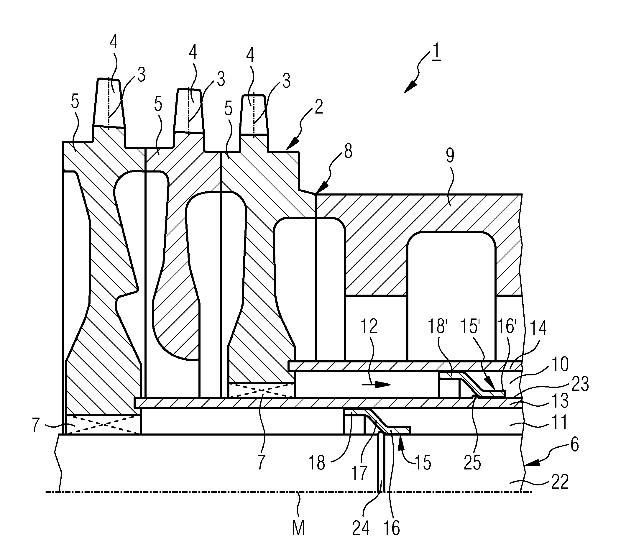
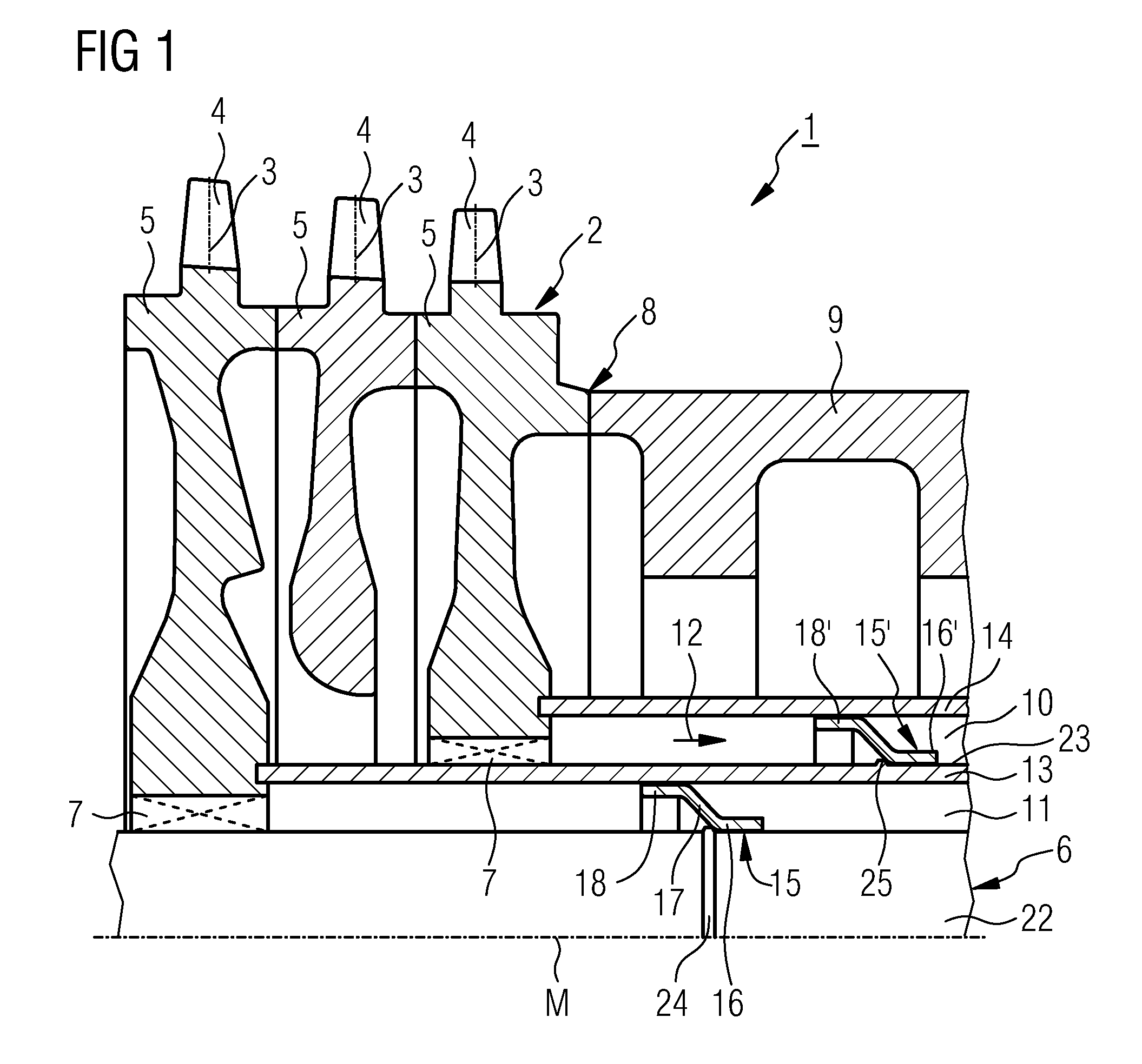
[0019]A rotor 2 of a multistage gas turbine 1, according to the broken-away sectional view in FIG. 1, comprises rotor disks 5 which are arranged in a plurality of planes and carry rotor blades 4 on the periphery. A tie-bolt 6 extends along centrally arranged recesses 7 in the rotor disks 5 through the compressor section of the gas turbine 1, which is on the left in FIG. 1, and is anchored, in a way which is not shown, in one of the rotor disks, which are not shown, or in a suitable rotor end section.
[0020]The pretensioned tie-bolt 6 presses the rotor disks 5 and also further rotor components of the turbine unit together in a form-fitting manner in a basically known way.
[0021]A center hollow shaft 9 is located axially next to the rotor disks 5 which are associated with the compressor of the gas turbine and with its opposite end, which is not shown, abuts against one of the rotor components of the turbine unit. Radially on the outside of this center hollow shaft 9, the combustion cham...
PUM
 Abstract
Description
Claims
Application Information