Turbine with at least one rotor which comprises rotor disks and a tie-bolt

a technology of rotor disks and rotors, which is applied in the direction of liquid fuel engines, machines/engines, mechanical equipment, etc., can solve the problems of increasing the length of the tie-bolt, destroying not only the tie-bolt but also the entire gas turbine, and free vibrating length, etc., to achieve sufficient pretensioning, simple installation, and increased damping or rigidity of the tie-bolt

Inactive Publication Date: 2010-06-10
SIEMENS AG
View PDF5 Cites 7 Cited by
  • Summary
  • Abstract
  • Description
  • Claims
  • Application Information

AI Technical Summary

Benefits of technology

[0008]The spacer according to the invention is basically a spring-ring with coaxially extending through-openings. The spring-ring increases the damping or rigidity of the tie-bolt in the rotating component / rotor and is sufficiently stable to hold the tie-bolt in its intended position regardless of the speed. The spring-ring can be simply installed, wherein a sufficient pretensioning is provided despite its spring characteristics. The functionality is ensured, therefore, even at high speeds.
[0009]The use of spacers additionally increases not only the natural frequency of the tie-bolt itself, but also the natural rigidity of all the components.
[0010]Also associated with this is that spacers according to the invention are basically also used in the region of cooling and separation pipes which encompass the tie-bolt with clearance in a specific axial section. The spacers in this case are located between the tie-bolt and the separation pipe which guides the cooling medium and delimits the annular passage on the outside. If necessary, a further annular passage can be formed in this connection between an inner or first separation pipe and an outer or second separation pipe so that then first spacers are provided between tie-bolt and inner separation pipe on the one hand and if necessary second spacers are provided between the inner separation pipe and an outer separation pipe, by means of which the tie-bolt can be supported in places against the radially further out rotor components which are associated with the rotor. As a result of the possibly even multiple supporting along its extent, the free vibratable length of the tie-bolt can be significantly shortened. With this measure, the margin between the natural frequency of the tie-bolt and the rotational frequency of the rotor can be increased, as a result of which its vibration tendency is significantly reduced. A safer operation of the gas turbine can therefore be ensured.
[0011]It is therefore possible with simple means to successfully achieve the aforementioned object.

Problems solved by technology

With increasing overall length, however, the freely vibrating length, i.e. the unsupported length of the tie-bolt, increases.
These can not only destroy the tie-bolt but also the entire gas turbine.

Method used


Image

  • Turbine with at least one rotor which comprises rotor disks and a tie-bolt
  • Turbine with at least one rotor which comprises rotor disks and a tie-bolt
  • Turbine with at least one rotor which comprises rotor disks and a tie-bolt

Examples


Embodiment Construction

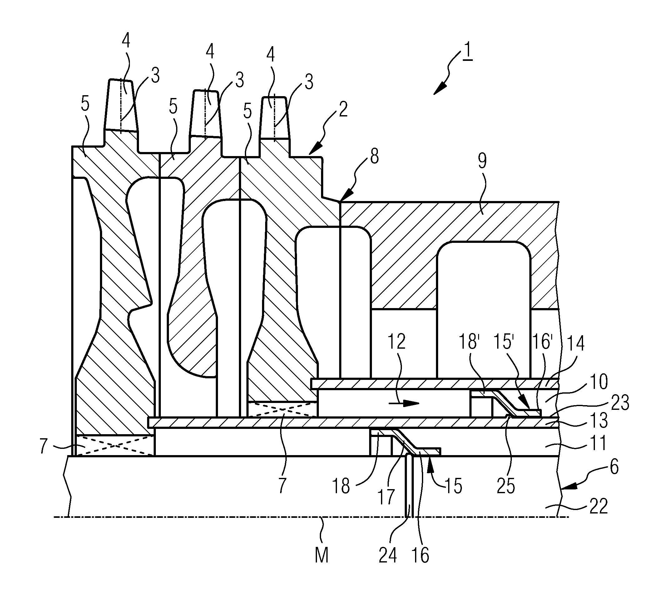
[0019]A rotor 2 of a multistage gas turbine 1, according to the broken-away sectional view in FIG. 1, comprises rotor disks 5 which are arranged in a plurality of planes and carry rotor blades 4 on the periphery. A tie-bolt 6 extends along centrally arranged recesses 7 in the rotor disks 5 through the compressor section of the gas turbine 1, which is on the left in FIG. 1, and is anchored, in a way which is not shown, in one of the rotor disks, which are not shown, or in a suitable rotor end section.

[0020]The pretensioned tie-bolt 6 presses the rotor disks 5 and also further rotor components of the turbine unit together in a form-fitting manner in a basically known way.

[0021]A center hollow shaft 9 is located axially next to the rotor disks 5 which are associated with the compressor of the gas turbine and with its opposite end, which is not shown, abuts against one of the rotor components of the turbine unit. Radially on the outside of this center hollow shaft 9, the combustion cham...


PUM


Abstract

A gas turbine is provided. The gas turbine includes at least one rotor, having rotor blades arranged on the periphery of rotor disks in a plurality of radial planes, and a tie-bolt extending along slots in the rotor disks and holding the rotor disks together as a unit. At least one annular spacer for fixing the position of the tie-bolt in relation to the center line of the rotor disks is also provided. The spacer includes through-openings that are arranged radially in relation to the tie-bolt or to its center line and that extend coaxially.

Description

CROSS REFERENCE TO RELATED APPLICATIONS[0001]This application is the US National Stage of International Application No. PCT / EP2008 / 051880, filed Feb. 15, 2008 and claims the benefit thereof. The International Application claims the benefits of European Patent Office application No. 07005082.8 EP filed Mar. 12, 2007, both of the applications are incorporated by reference herein in their entirety.FIELD OF INVENTION[0002]The invention refers to a gas turbine according to the claims.BACKGROUND OF INVENTION[0003]Multistage gas turbines with at least one rotating component, or rotor, which has rotor blades which are arranged in a plurality of radial planes on the periphery of rotor disks, are basically known in diverse design forms.[0004]Furthermore, it is known, at least in the case of gas turbines, to design the individual rotor disks with abutting end faces and in a form-fitting manner so that by means of a tie-bolt which extends through the rotor disks they can be held together as a u...

Claims


Application Information

Patent Timeline
Patent Type & Authority Applications(United States)
IPC IPC(8): F01D5/06F02C7/00
CPCF01D5/066F01D5/10F05D2260/96F05D2250/311F05D2230/64F05D2260/30F05D2250/182
Inventor BENKLER, FRANCOISEHEHALT, ULRICHHOELL, HARALDLOCH, WALTERSCHNEIDER, PETER-ANDREAS
Owner SIEMENS AG
Why Eureka
Try Eureka