Polymer composites possessing improved vibration damping

a polymer composite and vibration damping technology, applied in the field of vibration damping, can solve the problems of noise or motion associated with vibration that may distract and be uncomfortable for customers, and affect the operation of the vehicle, so as to increase the damping, increase the compliance, and control the effect of thermal expansion

Active Publication Date: 2012-12-13
THE BF GOODRICH CO
View PDF11 Cites 40 Cited by
  • Summary
  • Abstract
  • Description
  • Claims
  • Application Information

AI Technical Summary

Benefits of technology

[0021]Another aspect of the disclosed embodiments is a structure incorporating fiber-reinforced elastomer composite layers to increase damping, increase compliance and / or control thermal expansion.

Problems solved by technology
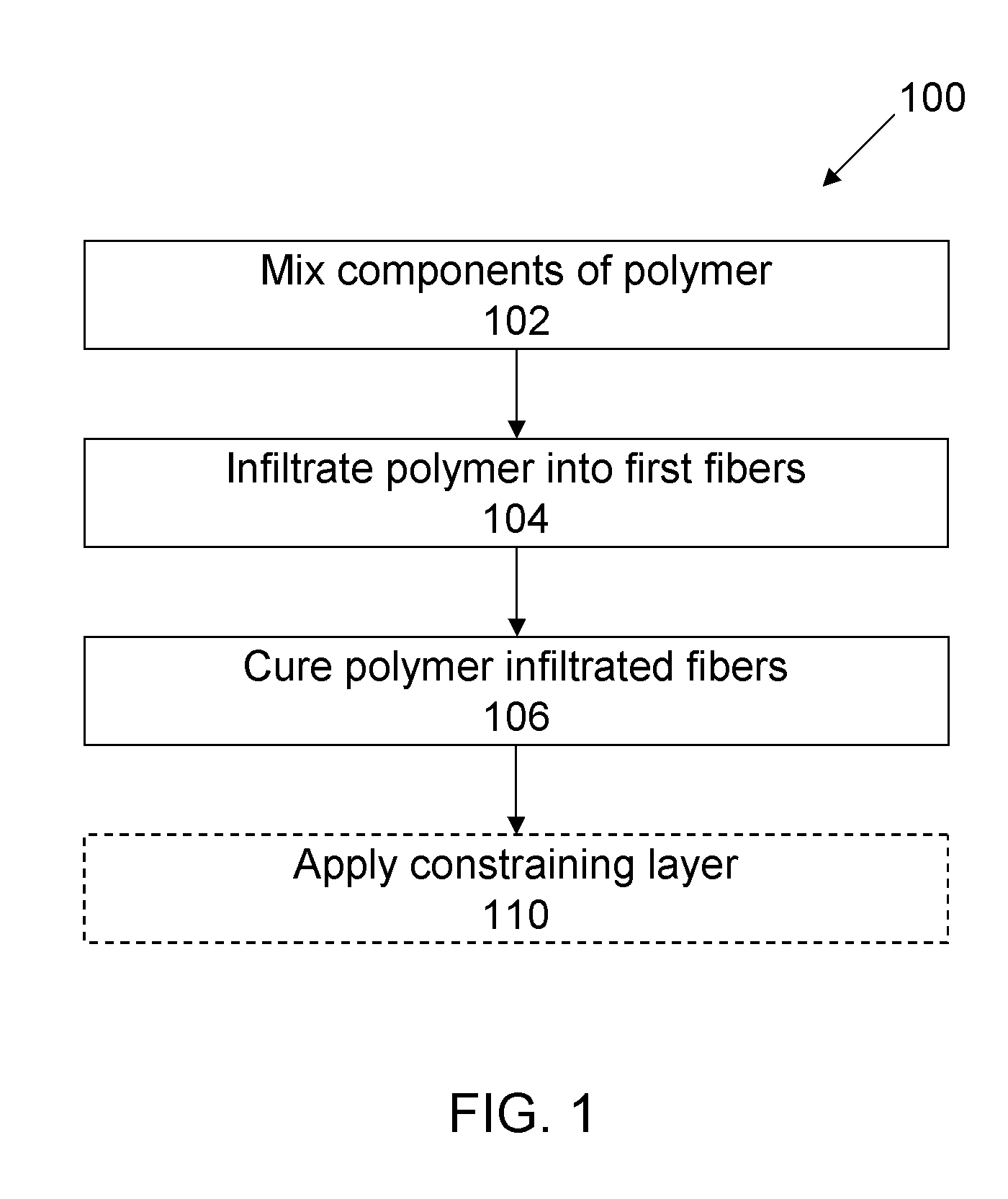
In one example, automobiles experience vibration during operation due to variations in the surface of the road.
In one aspect, mechanical vibrations may result in perceptible noise and / or motion.
In the context of consumer products, noise or motion associated with vibration may be distracting and uncomfortable to a customer.
This in turn may lead to a perception of poor quality of the product.
In another aspect, the oscillatory deformation associated with mechanical vibrations may lead to mechanical failure in a vibrating structure due to high cycle fatigue.
In another example, vibrations may induce undesirable acoustic levels in aircraft, rotor craft or marine vessels.
However, the loss factor of a viscoelastic material is not independent of the dynamic modulus.
While the amount of damping material employed in a damping application may be increased to compensate for the reduction in the damping per unit volume of the viscoelastic material, this approach is problematic.
In one aspect, adding more damping material to reduce vibrations occurring in a structure increases the cost of the viscoelastic material used.
In another aspect, adding more damping material to reduce vibrations occurring in a structure increases the total weight or size of the structure.
Either cost, weight or size increases may be prohibitive in certain applications.
For example, thermal expansion can alter the deform measurement tools, creating measurement error.
In another example, temperature changes can lead to residual stress and deformation when dissimilar materials with different coefficients of linear expansion are bonded together.

Method used


Image

  • Polymer composites possessing improved vibration damping
  • Polymer composites possessing improved vibration damping
  • Polymer composites possessing improved vibration damping

Examples


example 1

Effects of Fiber Reinforcement on Composite Damping Performance

[0099]The influence of the fiber configuration of the damping performance of the fiber-reinforced elastomer composites was investigated. FIG. 3 illustrates a plot of storage modulus and loss factor as a function of frequency for embodiments of the fiber-reinforced elastomer composites having carbon-fiber mats, 0° / 90° Innegra fibers, ±65° carbon-fiber plain weave, ±45° carbon-fiber plain weave, and ±28° carbon-fiber braid (with respect to the long axis of the composite), where the elastomer was polyurethane. A control elastomer, without reinforcement, was also tested for comparison.

[0100]The samples each possessed dimensions of about 3 mm thickness, about 10 mm width, and about 10 mm length. The fibers of the composites were oriented with respect to the long axis of the composite. The fiber volume fraction was about 50%.

[0101]As illustrated in FIG. 3, each of the composites exhibited a maximum loss factor greater than abo...

example 2

Dynamic Mechanical Analysis (DMA) of Composite and Damping Tile

[0103]Samples having dimensions of about 3.0 mm thickness, 10.0 mm width, and 9.5 mm length were examined using a Dynamic Mechanical Analyzer (DMA). A neat polyurethane elastomer (FIG. 4A) with no reinforcements was examined. A state-of-the-art damping tile (FIG. 4B) was examined. A composite with carbon fiber having a plain-weave configuration and a fiber orientation about ±65° in a volume fraction of about 50% (FIG. 4C) was examined. A composite with carbon fiber having a plain-weave configuration and a fiber orientation about ±45° in a volume fraction of about 50% (FIG. 4D) was examined. A composite with carbon fiber having a braid configuration and a fiber orientation about ±45° in a volume fraction of about 50% (FIG. 4E) was examined. A composite with carbon fiber having a plain-weave configuration and a fiber orientation about ±25° in a volume fraction of about 50% (FIG. 4F) was examined. A composite with carbon fi...

example 3

Modal Testing and Finite Element Analysis Validation of Dynamic Mechanical Analyzer Evaluation

[0107]Modal testing of the composite attached to aluminum beams was evaluated at frequencies from about 100 Hz to about 3000 Hz. One composite included 11 plies (about 0.1″ total thickness) of carbon fiber laminates, each having fibers oriented at about ±25° relative to the long axis of the composite. The viscoelastic composite was bonded between two aluminum beams having dimensions of about 17.75″×2.75″×0.25″ to provide shear deformation. To extend the measurement range, a second sandwich beam was constructed wherein the viscoelastic composite was bonded between two aluminum beams having dimensions about 3.75″×2.75″×0.25″. The temperature was maintained at about 23°.

[0108]The modal testing was evaluated using finite element analysis to calculate the resulting shear modulus G′ and loss factor. Finite element analysis was completed for both G13 and G23. The G13 calculations are equivalent to...


PUM

PropertyMeasurementUnit
dynamic shear modulusaaaaaaaaaa
Poisson's ratioaaaaaaaaaa
static Young's modulusaaaaaaaaaa

Abstract

Fiber-reinforced polymer composites possessing improved damping ability are provided. In one aspect, the fibers provide the composite with a relatively high dynamic modulus over a broad range of frequencies for a given temperature. In another aspect, the polymer may comprise a viscoelastic polymer possessing a relatively high loss factor for a given frequency and temperature. The polymer may be further tailored to control the center frequency at which the maximum loss factor of the polymer is achieved. The composite so formed exhibits a relatively small reduction in loss factor with significant increase in dynamic modulus over a broad range of frequencies for a given temperature. As a result, a structure damped by the composite exhibits a relatively high, constant loss factor as compared to conventional damping materials. Thus, embodiments of the disclosed composites dissipate significantly more energy during each vibration cycle than conventional damping materials.

Description

CROSS-REFERENCE TO RELATED APPLICATIONS[0001]This application claims the benefit of priority of U.S. Provisional Patent Application No. 61 / 496,547, entitled “POLYMER COMPOSITES HAVING IMPROVED FLEXURAL VIBRATION DAMPING”, filed on, Jun. 13, 2011. The entirety of this application is hereby incorporated by reference and should be considered a part of this specification.BACKGROUND[0002]1. Field[0003]Embodiments of the present disclosure pertain to vibration damping and, in particular, to polymer matrix composites that provide improved mechanical damping while retaining good mechanical and thermal properties.[0004]2. Description of the Related Art[0005]Vibration is commonly encountered in moving mechanical systems. In one example, automobiles experience vibration during operation due to variations in the surface of the road. In another example, cameras may vibrate when motion takes place around the mount to which the camera is attached.[0006]Controlling the degree to which a structure v...

Claims


Application Information

Patent Timeline
Patent Type & Authority Applications(United States)
IPC IPC(8): C08L75/04C08K7/06C08L63/00C08L27/14F16F7/00B32B37/02
CPCC08J5/042C08J5/043C08J5/046B29C70/88C08J2321/00B29K2019/00B29K2995/0091C08J5/24C08J5/243
Inventor CARTWRIGHT, CRAIGHERNANDEZ, JOSHUAHORNIG, NATHAN EDWARD
Owner THE BF GOODRICH CO
Why Eureka
Try Eureka