Veress needle with illuminated guidance and suturing capability

Active Publication Date: 2013-09-03
MOHAJER REZA S
View PDF23 Cites 5 Cited by
  • Summary
  • Abstract
  • Description
  • Claims
  • Application Information

AI Technical Summary

Benefits of technology

[0010]The preferred embodiment of the invention includes a cam mechanism supported at the proximal end of the instrument which allows the two jaws which make up the hook to be disposed in either an open position, in which the jaws are separated, or a closed position in which the jaws are closed, or closed about a suture. The mechanism includes a button at the proximal end of the instrument which may be depressed to move the hook between its opened and closed positions. With each depression, the hook is moved between its open and closed positions and remains in that state until the button is again depressed, moving the jaws to the other position. This allows a surgeon to manipulate the present instrument with a single hand.
[0011]Another aspect of the present invention, illustrated in connection with another embodiment of the invention, comprises an illuminating system for incorporation in a Veress needle assembly which allows the surgeon to visualize the progress of the trocar in forming a laparoscopic incision; aids in the visualization of major blood vessels in the incision area; and, in certain embodiments, provides illumination of the insufflated body cavity to aid in endoscopic visualization of the cavity. These illuminating systems can be incorporated in conventional Veress needle devices as well as the version incorporating the suturing capability.
[0014]The illumination at the distal end of the needle allows the position of the distal end to be visualized by the surgeon through the translucent body tissues. That is, the light from the distal end will pass through the body tissues and allow the surgeon to observe the distal tip of the trocar to determine when it clears the inner wall of the body cavity. It will also aid in identification of major blood vessels which might interfere with the formation of additional incisions required for laparoscopic surgery.

Problems solved by technology

One problem associated with the use of such Veress needle assemblies is determining when the needle has progressed through the wall of the body cavity and its distal end has emerged within the cavity.

Method used


Image

  • Veress needle with illuminated guidance and suturing capability
  • Veress needle with illuminated guidance and suturing capability
  • Veress needle with illuminated guidance and suturing capability

Examples


Embodiment Construction

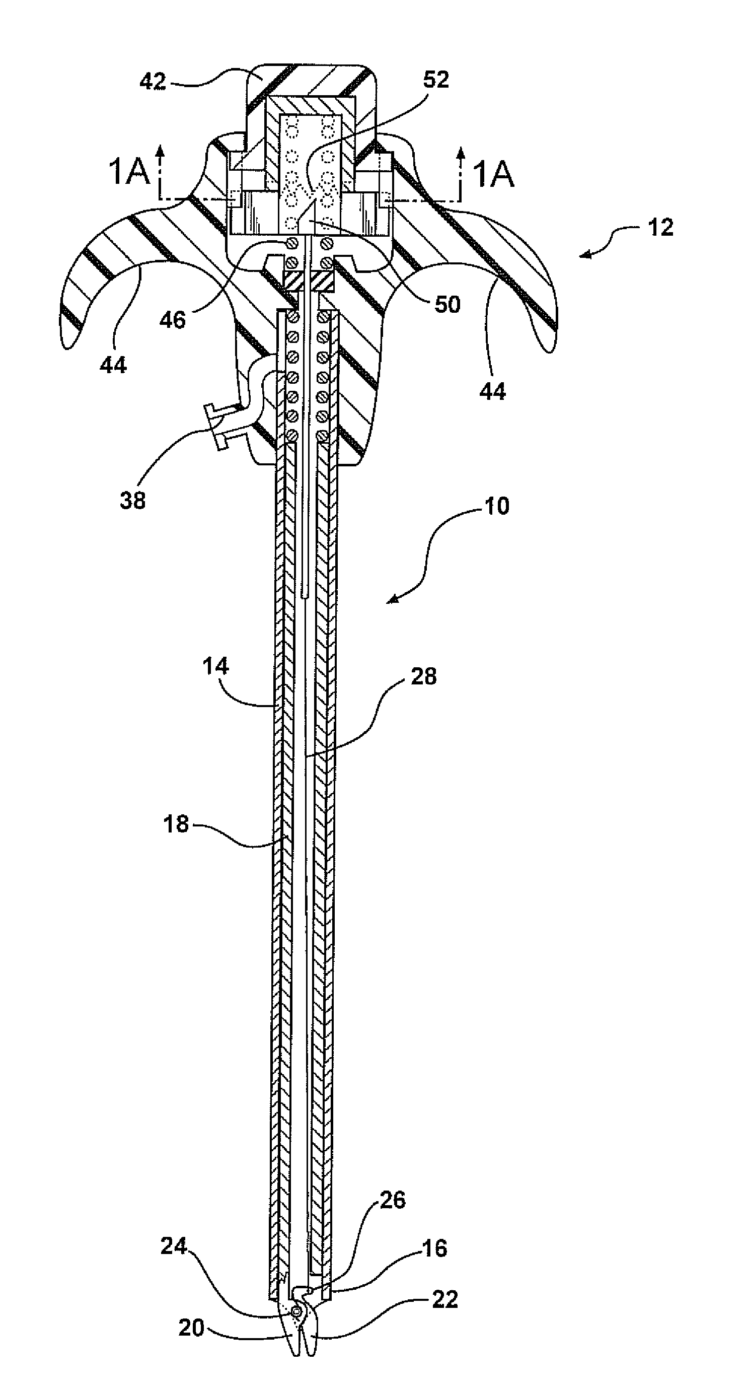
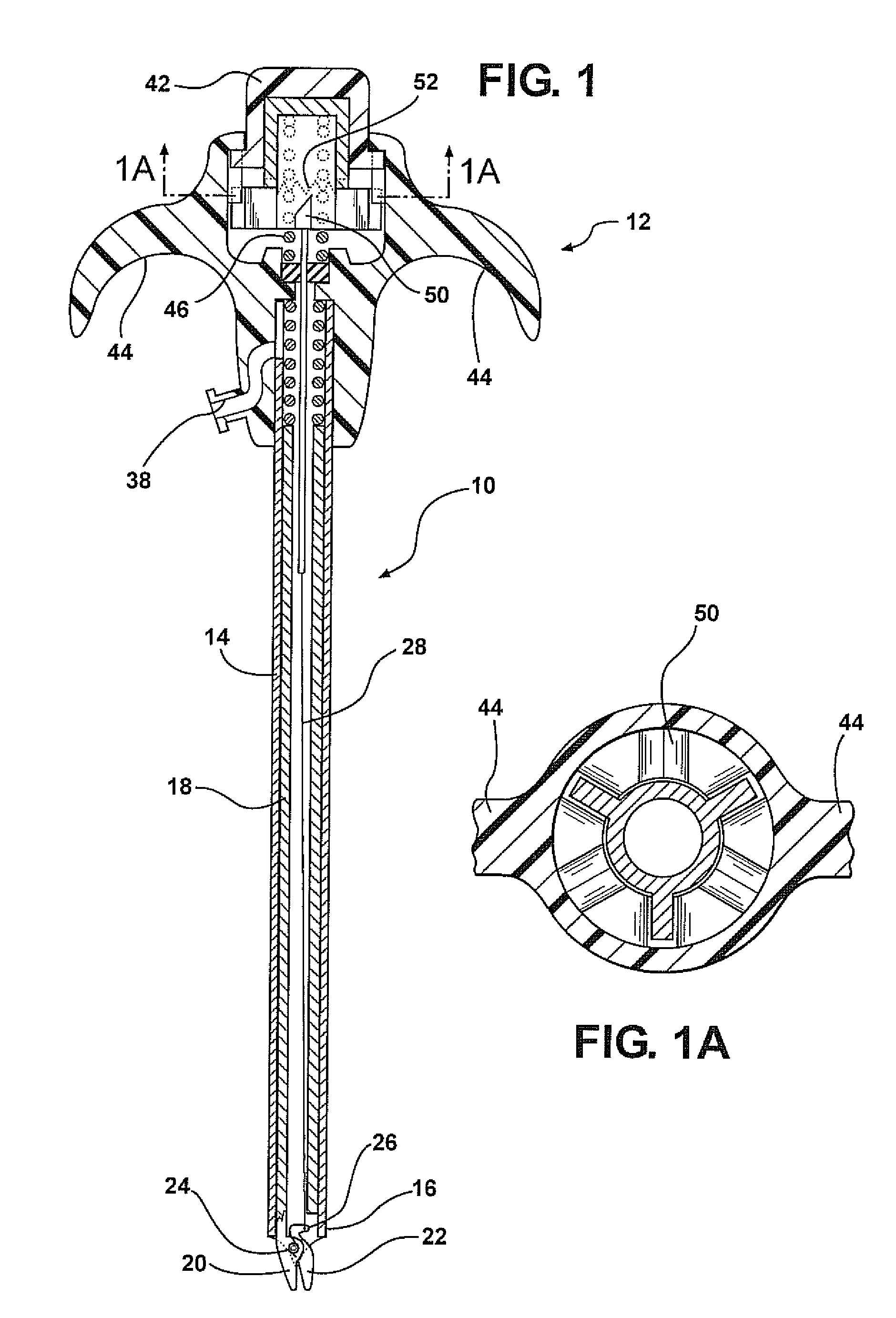
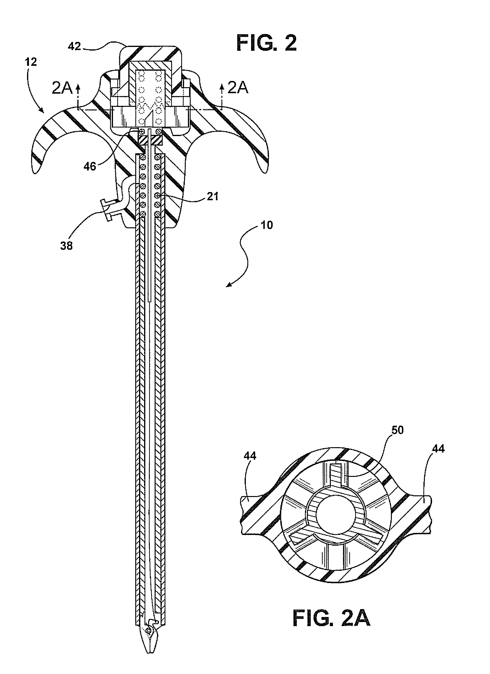
[0027]A preferred embodiment of the invention, illustrated in FIGS. 1 and 2, acts as a Veress needle to form an incision into a body cavity, as an insufflator to inject gas into the cavity, and as a suture manipulator to close up the incisions made during the endoscopic process.

[0028]The instrument, generally indicated at 10, has a handle 12 at the proximal end, which supports one end of the Veress needle, constituting an elongated cannula tube 14 with a sharpened trocar 16 at the distal end. A tubular needle having a diameter complementary to the diameter of the cannula 14 is supported within the cannula.

[0029]The distal end of the needle 18 carries one fixed jaw 20 of a suture engaging jaw set. The other jaw member 22 is pivotably connected to the jaw 20 at pivot point 24. A lever arm 26 formed on the jaw 22 connects to one end of a rod 28 which passes through the center of the needle with its proximal end terminating in the handle area 12 at an extension and retraction mechanism ...


PUM


Abstract

A laparoscopic instrument for forming an incision in a body cavity, insufflating the body cavity with gas, and suturing the incision at the completion of the surgery includes a set of jaws at the distal end of the Veress needle or cannula. The jaws are pivoted to one another for motion between an open position or a closed position in which they may be used to grasp a suture in the body cavity for removal from the cavity for knotting. A push mechanism at the proximal end of the instrument moves the jaws between their open and closed position on successive actuations of a pushbutton and retains them in that state until the next push. An illumination source is provided for the distal end of the instrument to provide illumination through the walls of the body cavity so that the surgeon can determine the degree of penetration of the instrument into the body cavity and can identify any major arteries which should be avoided in the formation of other laparoscopic openings.

Description

CROSS-REFERENCE TO RELATED APPLICATION[0001]This application claims priority of U.S. Provisional Patent Application Ser. No. 61 / 146,974 filed Jan. 23, 2009, which is incorporated herein by reference.FIELD OF THE INVENTION[0002]This invention relates to an instrument for use in the practice of laparoscopic surgery and more particularly to such a device which has utility in forming an incision, insufflating the underlying body cavity and suturing the incision at the completion of the surgery.BACKGROUND OF THE INVENTION[0003]In the practice of minimally invasive laparoscopic surgery it is common to make a small incision through the skin and underlying tissue of the patient adjacent the internal surgical site using a Veress needle. These needles include a tubular outer cannula with a sharpened distal end and an inner hollow cylindrical needle which terminates in a blunt end. A spring assembly urges the needle to a position in which the blunt end of the needle is extended beyond the cutt...

Claims


Application Information

Patent Timeline
Patent Type & Authority Patents(United States)
IPC IPC(8): A61M5/178
CPCA61B17/3474A61B17/0483A61B17/29A61B17/295A61B2017/00349A61B2017/00353A61B2019/521A61B2017/00663A61B2090/309
Inventor MOHAJER, REZA S.
Owner MOHAJER REZA S
Why Eureka
Try Eureka