Ankle-joint endoprosthesis

an endoprosthesis and ankle joint technology, applied in the field of ankle joint endoprosthesis, to achieve the effect of avoiding or alleviating imbalan

Inactive Publication Date: 2013-11-26
ENCORE MEDICAL
View PDF26 Cites 6 Cited by
  • Summary
  • Abstract
  • Description
  • Claims
  • Application Information

AI Technical Summary

Benefits of technology

[0004]The object of the invention is to avoid or alleviate an imbalance between, on the one hand, the anatomical or surgical circumstances and, on the other hand, the prosthesis.

Problems solved by technology

However, it has been found that, after surgery, the collateral and medial ligaments of the joint often have different tensioning, which can cause problems.
This may be due to irregularities of the anatomy or to the fact that the operating surgeon has chosen an unfavorable orientation of the resection surface provided on the shin bone for connection to the prosthesis.

Method used


Image

  • Ankle-joint endoprosthesis
  • Ankle-joint endoprosthesis

Examples


Embodiment Construction

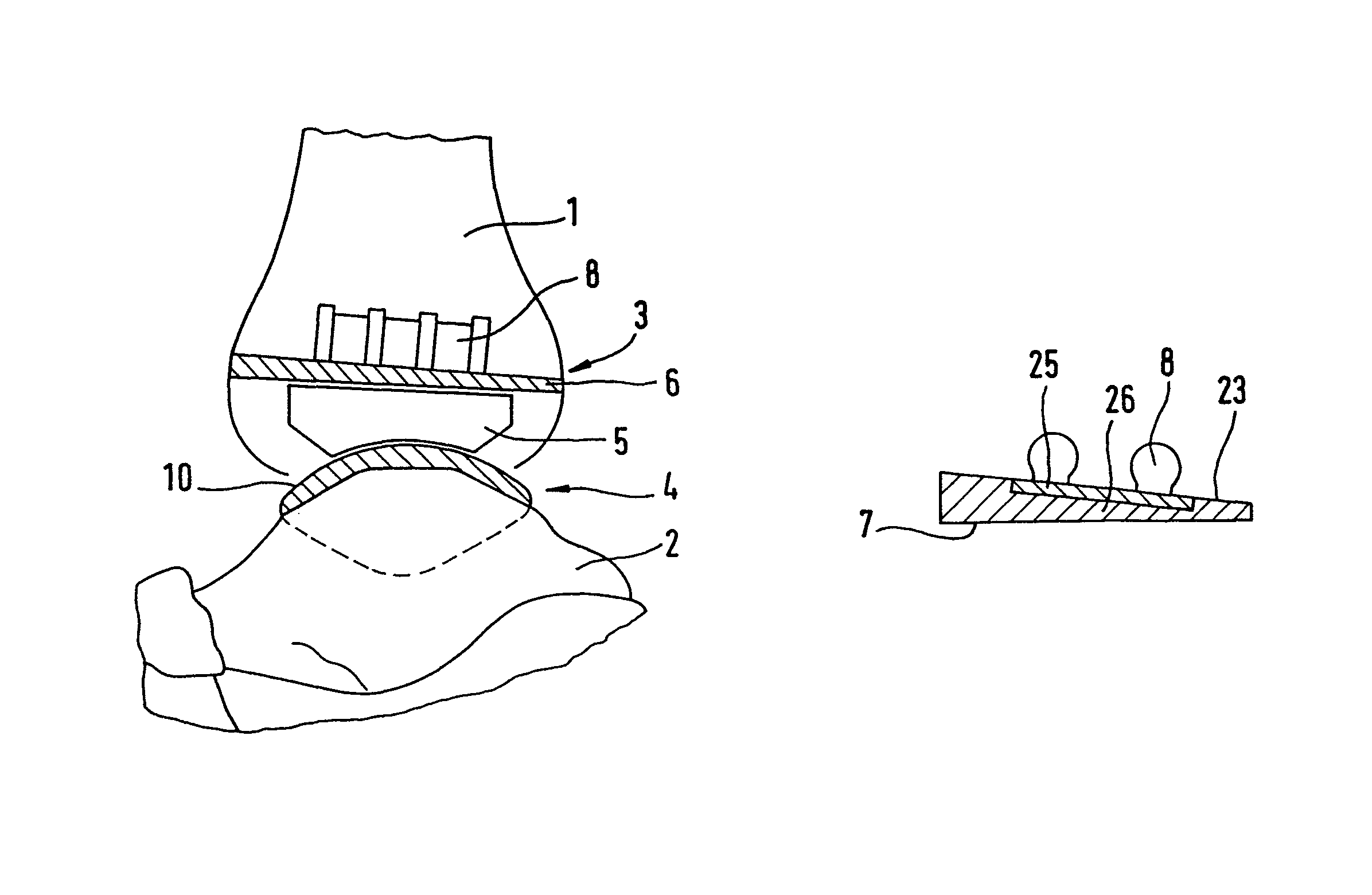
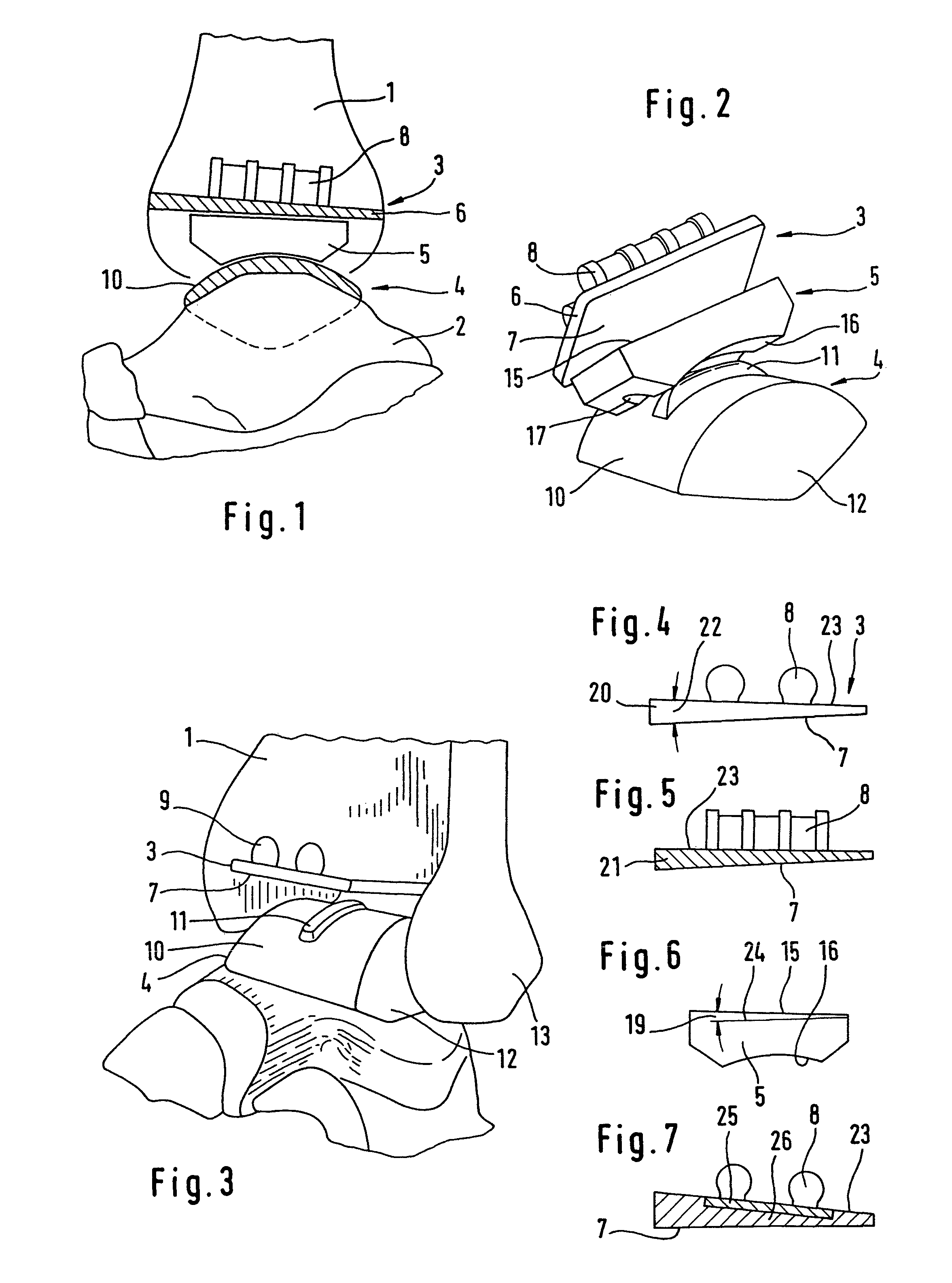
[0020]The prosthesis comprising the upper component 3, the lower component 4 and the intermediate part 5 is to be arranged between the shin bone 1 and the ankle bone 2. The upper component 3 has a plate-shaped part 6 whose bottom face 7 forms a planar slide surface. Projections 8 are used for securing it in corresponding resection recesses 9 in the shin bone 1.

[0021]The lower component 4 forms a convexly curved slide surface 10 which can be designed cylindrically or conically. It carries a rib 11 which lies in the direction of the relative movement of the intermediate part during flexion and extension movement. The lower component additionally has lateral facets 12 for interaction with corresponding slide surfaces of the shin bone 1 and of the calf bone 13.

[0022]The intermediate part 5 has a planar top face 15 matching the slide surface 7, and a bottom slide surface 16 which is designed to complement the slide surface 10 of the lower component 4. It includes a groove 17 for receivin...


PUM


Abstract

An endoprosthesis for replacing the ankle joint includes a lower component which is configured to be connected to the ankle bone, an upper component which is configured to be connected to the shin bone, and an intermediate part which forms a slide joint both with the lower and upper components. The intermediate part, which is wedge-shaped in sagittal section, is provided in order to compensate for anatomical or surgical irregularities. The upper component can also be wedge-shaped in frontal or sagittal section.

Description

CROSS REFERENCE OF RELATED APPLICATIONS[0001]This application is a continuation of U.S. application Ser. No. 10 / 567,580, filed Feb. 8, 2006, now abandoned, which is a National Stage application of PCT / EP2003 / 009489, filed Aug. 27, 2003, the contents of which are incorporated herein by reference in their entireties.FIELD AND BACKGROUND OF THE INVENTION[0002]To replace the ankle joint, an endoprosthesis is known comprising a component to be connected to the ankle bone, a component to be connected to the shin bone, and an intermediate part (DE-U-88 12 806, brochure “LINK S.T.A.R. Totale Sprunggelenk-prothese [H. Kofoed] from Waldemar Link (GmbH & Co.), Hamburg). The ankle bone component and the intermediate part interact via slide surfaces which permit flexion and extension in the sagittal plane. The shin bone component and the intermediate part form interacting slide surfaces which permit a rotation about the vertical axis of the endoprosthesis. They can be of a plane design in order ...

Claims


Application Information

Patent Timeline
Patent Type & Authority Patents(United States)
IPC IPC(8): A61F2/42A61F2/00A61F2/30
CPCA61F2/30734A61F2/4202A61F2002/30153A61F2002/30158A61F2002/30233A61F2002/30266A61F2002/3028A61F2002/30324A61F2002/30382A61F2002/30395A61F2002/30398A61F2002/30433A61F2002/30604A61F2002/30616A61F2002/30736A61F2002/3082A61F2002/30878A61F2002/30881A61F2002/30892A61F2002/30934A61F2220/0025A61F2220/0033A61F2220/0041A61F2230/0019A61F2230/0026A61F2230/0063A61F2230/0069A61F2230/0082A61F2250/0036A61F2310/00011A61F2310/00179A61F2002/30331A61F2002/30281A61F2002/30621
Inventor KOFOED, HAKONKELLER, ARNOLDLINK, HELMUT D.
Owner ENCORE MEDICAL
Why Eureka
Try Eureka