
Nail positioning member of nail slot of nail gun

a positioning member and nail gun technology, which is applied in the direction of nailing tools, stapling tools, manufacturing tools, etc., can solve the problems of nail gun jamming, difficulty in reducing manufacture cost and assembly time, etc., and achieve the effect of preventing nail jamming and preventing nails

Inactive Publication Date: 2014-02-11
ROBERT BOSCH TOOL +1
View PDF24 Cites 4 Cited by
  • Summary
  • Abstract
  • Description
  • Claims
  • Application Information

AI Technical Summary

Benefits of technology

The present invention aims to simplify the design and arrangement of the nail positioning member to prevent complications. It also seeks to prevent nails from moving laterally, being inclined or shaking, which can lead to the nail getting jammed in the nail gun. The invention achieves this by using a spring to push or discharge the protruding portion of the nail pushing piece, which in turn drives the nail pushing portion to oscillate to a first or second position, and control the height of the nail slot to limit the movement of the nails. This solution addresses the issue of the nail pressing piece focuses force on one end of the pressing strip away from the perforation, which may cause the pressing strip swung and the nail slot not completely opened. Overall, the invention simplifies the manufacturing process, reduces costs, and improves the reliability and efficiency of the nailing process.

Problems solved by technology

The disadvantage is that a plurality of elastic strip members is complicated for design and arrangement, which makes it difficult to decrease the manufacture cost and assembly time.
In addition, the stripe members close to the nail head only have the function of separating the nail slot, which causes nails from moving laterally, being inclined or shaking because of the different dimensional accuracy of the nails and as a result, causes the nail jammed in the nail gun.
The disadvantage is that the point of application of a force by the nail pushing piece to the pressing strip 7d focuses on the protruding portion 73d of one end of the pressing strip 7d away from the perforation 12d.

Method used


Image

  • Nail positioning member of nail slot of nail gun
  • Nail positioning member of nail slot of nail gun
  • Nail positioning member of nail slot of nail gun

Examples


Embodiment Construction

[0028]Hereinafter, the present invention will be described in detail with reference to the accompanying drawings. It should be understood that drawings do not limit the scope of the present invention.

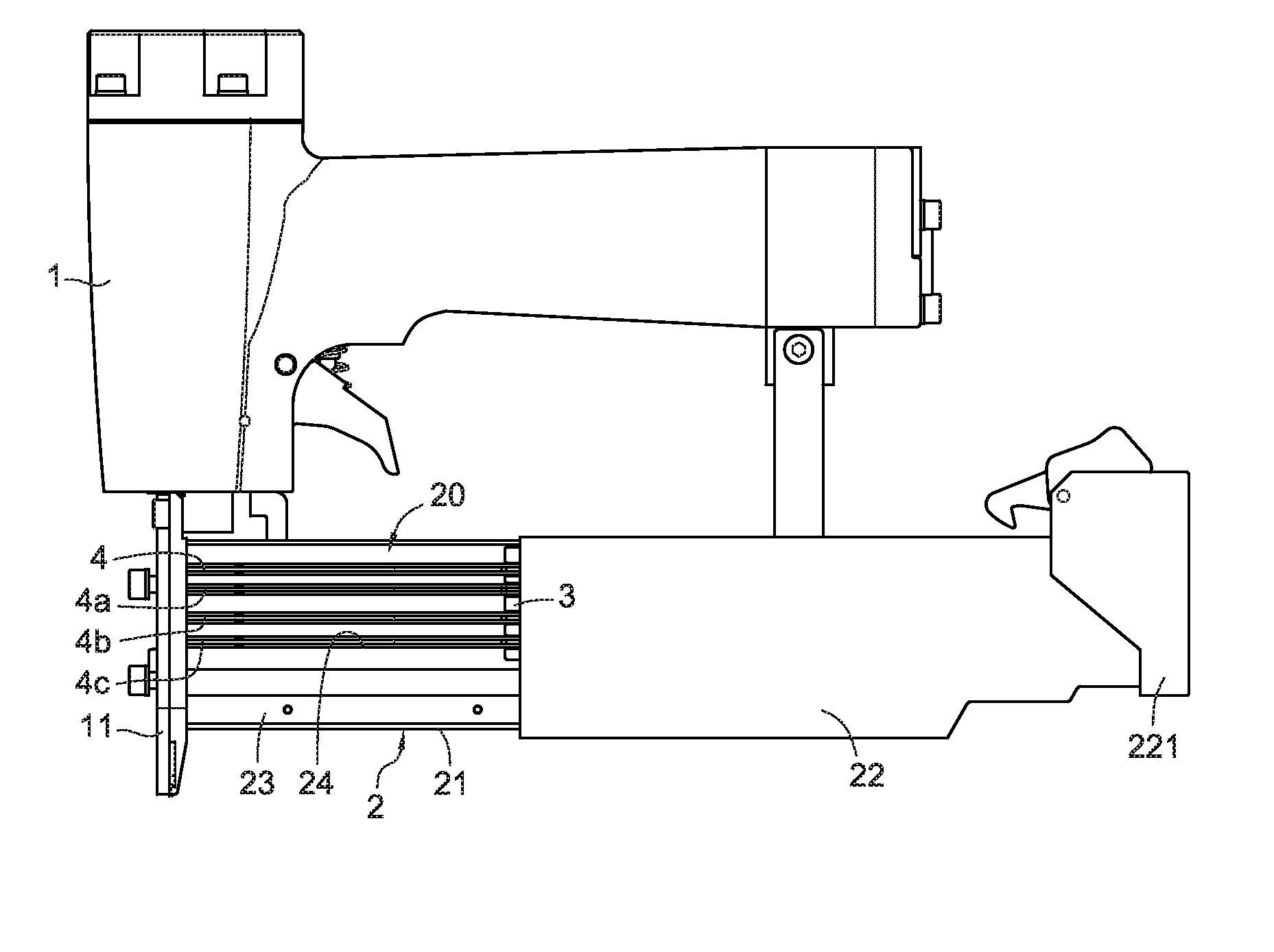
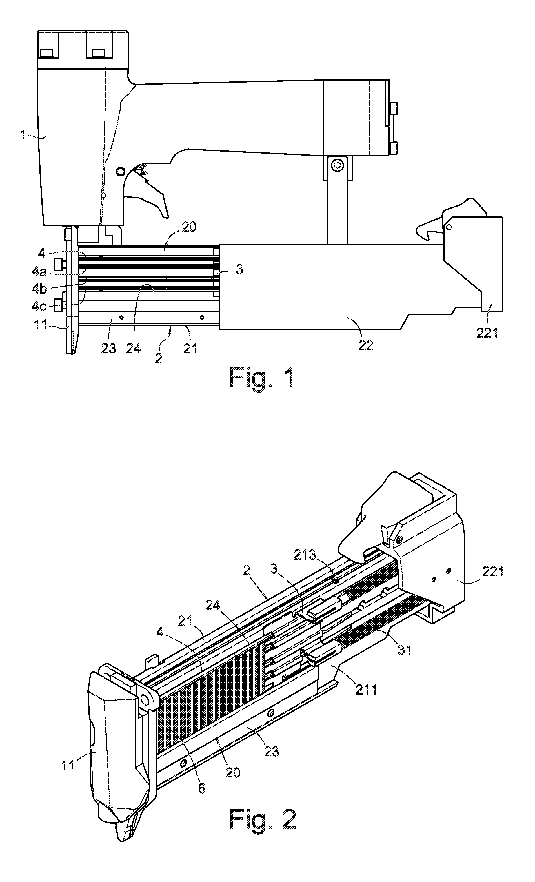
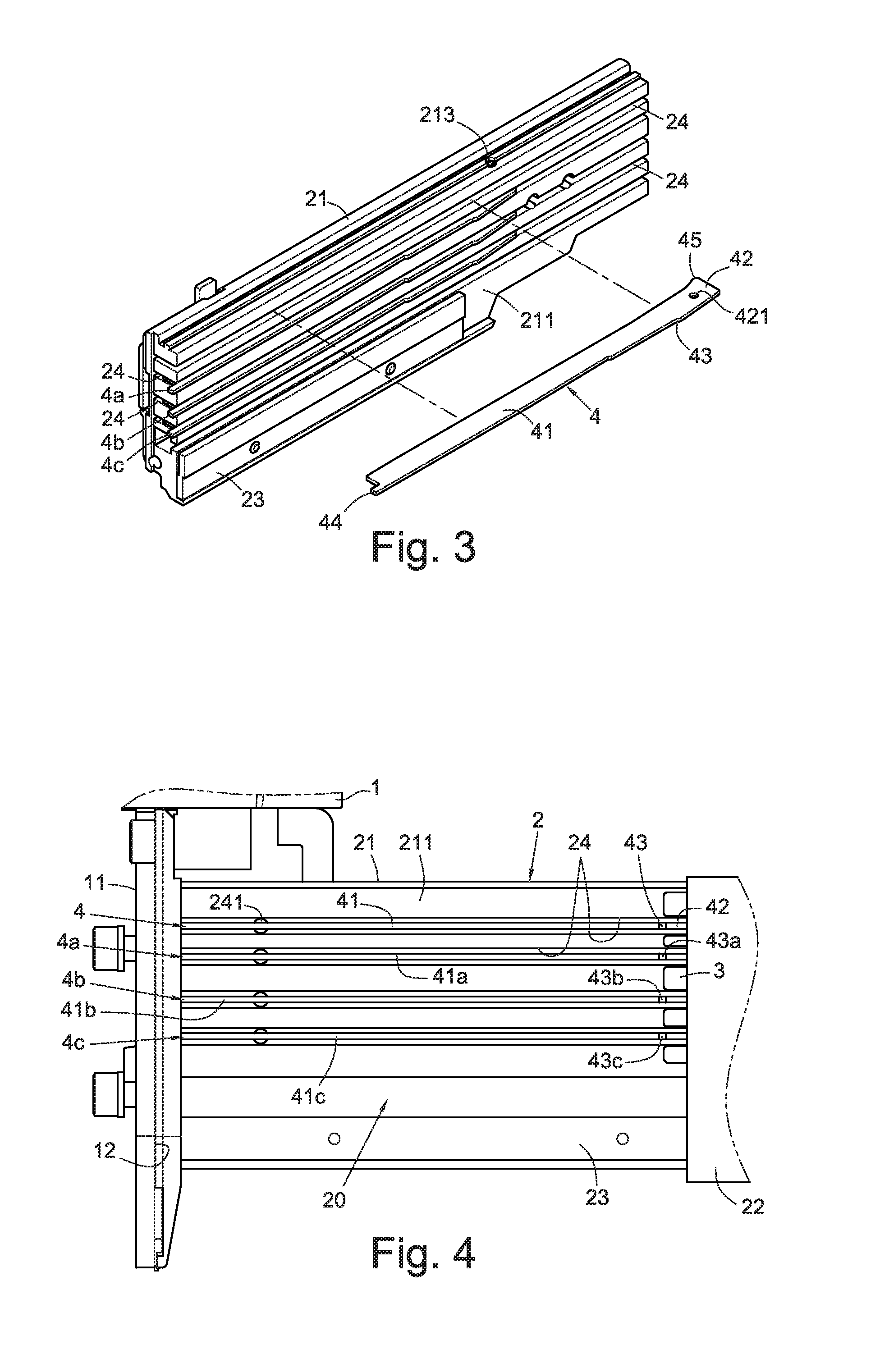
[0029]FIG. 1 is a front view of one embodiment of the present invention. As shown in FIG. 1 accompanying with FIG. 2 and FIG. 4, a nail positioning member of a nail slot of a nail gun may comprise a magazine 2, a nail pushing piece 3, a plurality of horizontal slot channels 24 parallel to each other, a plurality of positioning pieces 4, 4a, 4b, 4c provided in the slot channels 24 and a plurality of compressed spring 5. The magazine 2 may be provided on the side of a gun muzzle 11 which is at the bottom of the gun body 1 of the nail gun. The magazine 2 may include a base 21 connected to the side of the muzzle 11 and a sliding cover 22 slidably assembled to an inside wall 211 of the base 21. An anti-abrasive board 23 may be provided at the bottom of the inside wall 211 of the base 21. The...


PUM


Abstract

A nail positioning member of a nail slot of a nail gun includes a magazine including a horizontal nail slot connected with a perforation for nailing; a nail pushing piece slidably assembled to the nail slot; a plurality of horizontal slot channels parallel to the nail slot; and a plurality of positioning pieces, respectively pivotally assembled to the slot channels to block the head of the nails. The positioning piece forms a protruding portion in a movement path of the nail pushing piece, to be pushed by the nail pushing piece and to drive the positioning piece to oscillate in the direction of the slot channel in order to open the nail slot for placing the nails.

Description

BACKGROUND[0001]1. Technical Field[0002]The present invention relates to a nailing positioning member of a nail slot of a nail gun. More particularly, the present invention relates to a nail slot inside of a magazine, a nail pushing piece inside of the nail slot, slot channels inside of the magazine and positioning pieces.[0003]2. Related Art[0004]The gas-driven nail gun is a tool which uses high pressure to drive the nail. Nail guns in the market are usually capable of using nails of different length. Users can choose, according to the position or shape of the work piece to be nailed, a row of nails of appropriate length to fill into the magazine of the nail gun to drive the nail into the surface of the work piece. To use a single magazine to fill in a row of nails in different length, traditionally a nail positioning device is provided in a horizontal nail slot connected to a perforation for nailing in the magazine. The nail positioning device is provided to adjust the height of t...

Claims


Application Information

Patent Timeline
Patent Type & Authority Patents(United States)
IPC IPC(8): B25C5/02B25C5/06
CPCB25C1/005B25C5/1658
Inventor WU, I-TSUNGHUANG, PO-FENGZHANG, YI-ZHUO
Owner ROBERT BOSCH TOOL
Learn More