Engine stop control device

a control device and engine technology, applied in electrical control, hybrid vehicles, instruments, etc., can solve the problems of difficult to sufficiently compensate, difficult to reduce the control load of the alternator, and inability to exert a sufficient effect to so as to reduce the variation in the engine rotation stop position and improve the restarting performan

Active Publication Date: 2014-03-18
DENSO CORP
View PDF25 Cites 11 Cited by
  • Summary
  • Abstract
  • Description
  • Claims
  • Application Information

AI Technical Summary

Benefits of technology

[0009]The present invention has been made in consideration of the above circumstances. Therefore, it is an object of the present invention to provide an engine stop control device that is capable of controlling torque of an electric machinery to accurately conform an engine rotation behavior to a target trajectory of engine stop control by accurately setting the target trajectory and that is capable of accurately controlling an engine rotation stop position to a target stop position.
[0011]The influence of the compression arises in a very low rotation range immediately before the engine rotation stops. Therefore, by setting the target trajectory extending to the target rotation speed at the reference point set at the position preceding the target stop position by the predetermined crank angle as in the present invention, the target trajectory can be set in the range preceding the very low rotation range in which the influence of the compression arises. Thus, the engine rotation behavior can be controlled with the electric machinery without being affected by the compression during the engine rotation stop behavior.
[0012]The control of the torque of the electric machinery becomes difficult immediately before the reference point. Therefore, in consideration of this point, according to the present invention, the torque of the electric machinery is controlled such that the energy deviation between the target trajectory and the engine rotation behavior becomes zero at the position preceding the reference point by the second predetermined crank angle. Accordingly, the engine rotation behavior can be accurately conformed to the target trajectory with the torque of the electric machinery by using the range where the torque of the electric machinery can be efficiently controlled before the reference point is reached. Thus, the actual rotation speed can be accurately conformed to the target rotation speed at the reference point. The target rotation speed at the reference point is set at the engine rotation speed at the reference point necessary for stopping the engine rotation at the target stop position from the reference point. That is, the setting is made such that the target stop position is located on an extended line of the target trajectory extending to the reference point. Therefore, as the actual rotation speed can be accurately conformed to the target rotation speed at the reference point according to the present invention, the actual stop position of the engine rotation can be accurately conformed to the target stop position.
[0013]In a second example embodiment of the invention, the target rotation speed at the reference point may be set to or under lower limit rotation speed of a rotation speed range, in which the torque of the electric machinery is generated, and the position preceding the reference point by the second predetermined crank angle (i.e., position where energy deviation between target trajectory and engine rotation behavior becomes zero) may be set at a position where the engine rotation speed coincides with the lower limit rotation speed of the rotation speed range, in which the torque of the electric machinery is generated. With such the construction, the influence of the torque of the electric machinery does not arise in the engine rotation behavior extending from the reference point to the target stop position. Thus, the error in the stop position due to the torque of the electric machinery can be eliminated. Moreover, the position where the energy deviation between the target trajectory and the engine rotation behavior becomes zero is set at the position where the engine rotation speed coincides with the lower limit rotation speed of the torque generation rotation speed range of the electric machinery. Therefore, the engine rotation behavior can be accurately conformed to the target trajectory by using the range, where the torque of the electric machinery can be efficiently outputted, as efficiently as possible. Alternatively, the present invention may be implemented by setting the position where the energy deviation between the target trajectory and the engine rotation behavior becomes zero at a position where the engine rotation speed becomes rotation speed slightly higher than the lower limit rotation speed of the torque generation rotation speed range of the electric machinery.
[0016]As in a fourth example embodiment of the invention, the engine stop control may be performed by fixing the torque of the electric machinery at a constant value when an absolute value of the energy deviation at the start of the engine stop control is smaller than a predetermined value, and the engine friction may be learned based on the engine rotation behavior during the engine stop control. When the absolute value of the energy deviation at the start of the engine stop control is small, the engine rotation can be stopped at the target stop position with a certain accuracy even without performing the feedback control of the torque of the electric machinery. Therefore, in this case, the feedback control is prohibited and the engine friction is learned based on the engine rotation behavior. Thus, the engine friction can be learned with high accuracy without being affected by the torque fluctuation of the electric machinery due to the feedback control. Alternatively, the present invention may be implemented by omitting the function to learn the engine friction and by calculating the engine friction based on experimental data or design data beforehand.

Problems solved by technology

Therefore, the control of the alternator load is rough and it is difficult to sufficiently compensate a variation in an engine rotation behavior during an engine stop process.
Therefore, it is thought that the control device of Patent document 1 cannot reduce the variation in the engine rotation stop position sufficiently and cannot exert a sufficient effect to improve the restarting performance.
Therefore, accuracy of the target trajectory worsens correspondingly.
However, a characteristic of a friction or compression governing the engine rotation stop behavior changes due to oil temperature, oil degradation, aging change and the like.
However, it is difficult to learn the compression and the friction from the stop position error separately.

Method used


Image

  • Engine stop control device
  • Engine stop control device
  • Engine stop control device

Examples


Embodiment Construction

[0041]Hereinafter, an embodiment embodying the best mode for implementing the present invention will be described.

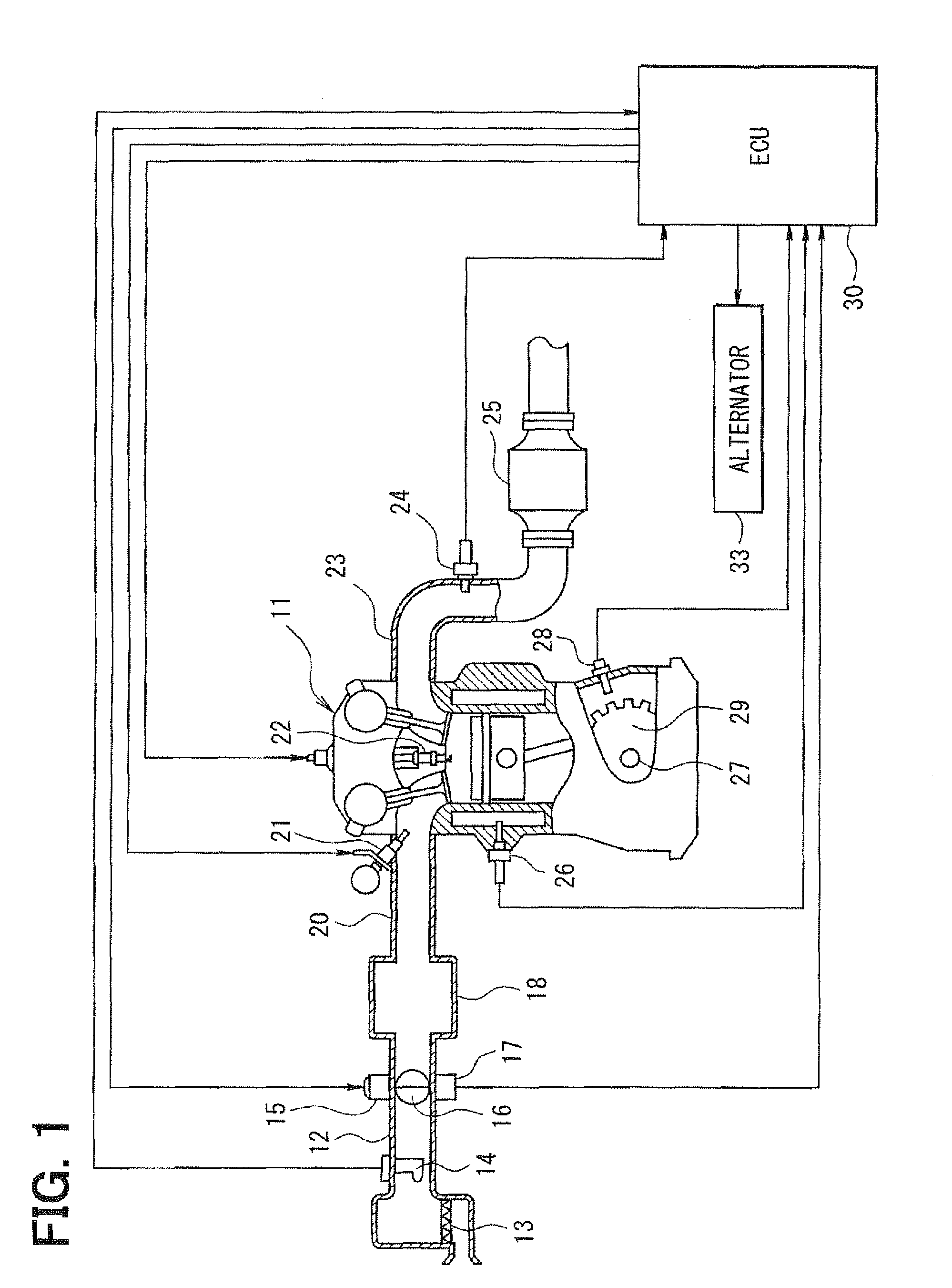
[0042]First, a schematic construction of entirety of an engine control system will be explained with reference to FIG. 1.

[0043]An air cleaner 13 is arranged in the most upstream portion of an intake pipe 12 of an internal combustion engine 11. An airflow meter 14 sensing intake air quantity is provided downstream of the air cleaner 13. A throttle valve 16, whose opening degree is regulated by a motor 15, and a throttle position sensor 17 sensing the opening degree of the throttle valve 16 (throttle opening) are provided downstream of the airflow meter 14. A surge tank 18 is provided downstream of the throttle valve 16. An intake manifold 20 that introduces air into each cylinder of the engine 11 is connected to the surge tank 18. An injector 21 that injects fuel is provided near an intake port of the intake manifold 20 of each cylinder. A spark plug 22 is provided to a c...


PUM


Abstract

Target rotation speed at a reference point set at TDC slightly preceding a target stop position of engine rotation is set. A target trajectory of an engine rotation behavior extending since an engine rotation stop behavior starts until the target rotation speed at the reference point is reached is calculated based on the target rotation speed at the reference point and an engine friction. Torque of an alternator is controlled to conform the engine rotation behavior to the target trajectory during the engine rotation stop behavior. Generation of the torque of the alternator stops at a position preceding the reference point by a predetermined crank angle. Therefore, the torque of the alternator is controlled such that an energy deviation between the target trajectory and the engine rotation behavior becomes zero at the position preceding the reference point by the predetermined crank angle.

Description

CROSS REFERENCE TO RELATED APPLICATION[0001]This application is the U.S. National Phase of International Application No. PCT / JP2009 / 003565 filed on Jul. 29, 2009, which designated the U.S. and is based on and incorporates herein by reference Japanese Patent Application No. 2008-205951 filed on Aug. 8, 2008.TECHNICAL FIELD[0002]The present invention relates to an engine stop control device having a function to control an engine rotation stop position (stop crank angle) when an engine stops.BACKGROUND TECHNOLOGY[0003]In recent years, as described in Patent document 1 (JP-A-2005-315202), there has been a vehicle mounted with an engine automatic stop-start system (idle stop system) that performs control for increasing a target current value of an alternator to an initial value set at a large value beforehand and then decreasing the target current value when an engine is stopped automatically, aiming to control an engine rotation stop position (stop crank angle) into a crank angle range,...

Claims


Application Information

Patent Timeline
Patent Type & Authority Patents(United States)
IPC IPC(8): F02N11/08G06F19/00G06G7/70F02D29/02F02D45/00F02D17/00
CPCF02D2200/1015F02D29/02B60W10/06Y02T10/6286B60W2510/0685F02D2041/0095B60W10/08B60W20/00F02N19/005F02D41/2451F02D2250/24F02D41/042F02D17/04F02N2019/008Y02T10/62B60W20/15B60W2510/0638
Inventor NAKAI, YASUHIROYOSHIHARA, MASATOMOOKAMURA, KOUJI
Owner DENSO CORP
Why Eureka
Try Eureka