
Quasi-resonant controlled switching regulator and the method thereof
a switching regulator and quasi-resonant technology, applied in the direction of electric variable regulation, process and machine control, instruments, etc., can solve the problems of high switching loss and efficiency variation with load or input voltage, high switching frequency, and consequent emi (electromagnetic interference) problems
- Summary
- Abstract
- Description
- Claims
- Application Information
AI Technical Summary
Benefits of technology
Problems solved by technology
Method used
Image

Examples
Embodiment Construction
[0030]In the present disclosure, numerous specific details are provided, such as examples of circuits, components, and methods, to provide a thorough understanding of embodiments of the disclosure. Persons of ordinary skill in the art will recognize, however, that the disclosure can be practiced without one or more of the specific details. In other instances, well-known details are not shown or described to avoid obscuring aspects of the disclosure.
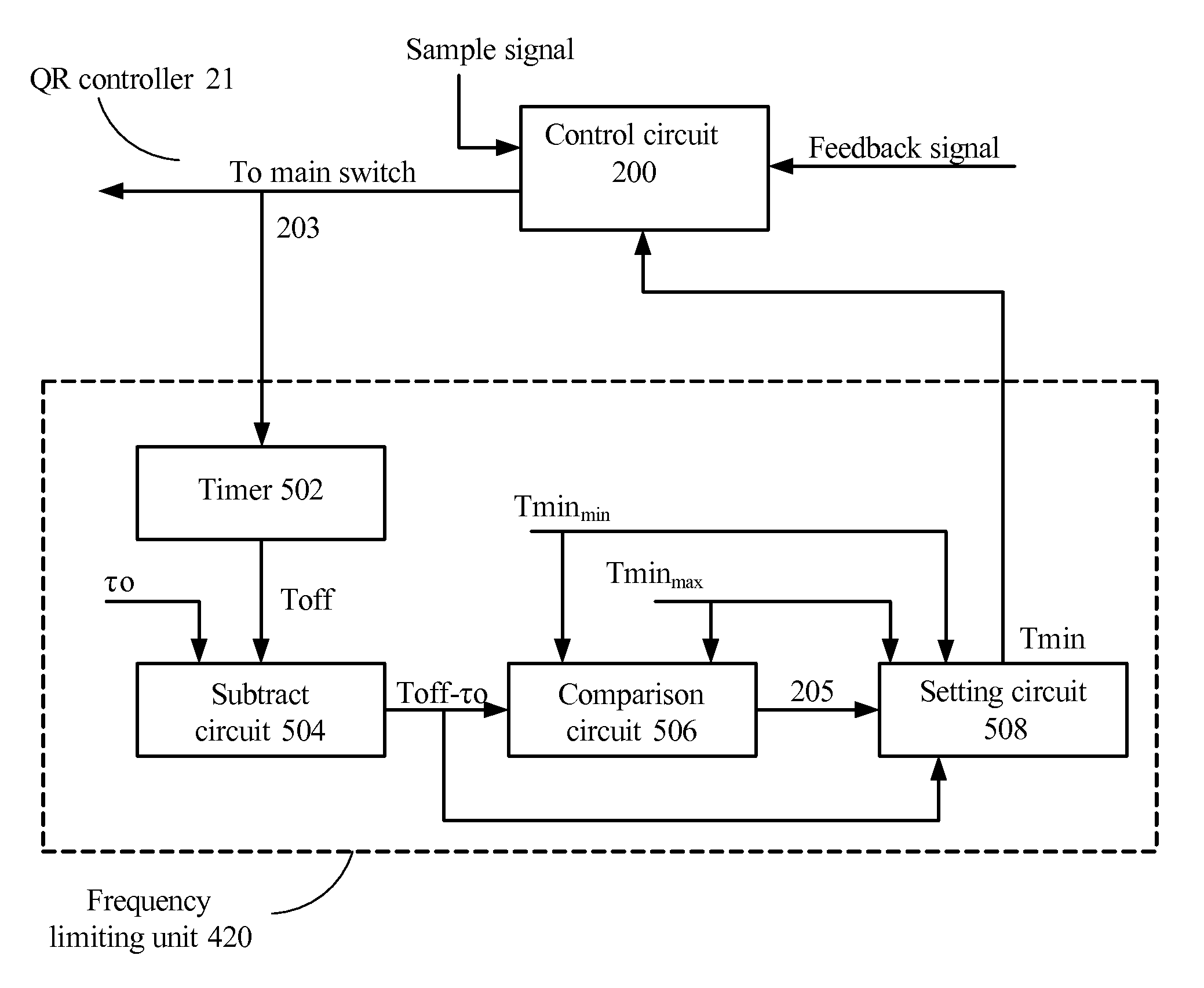
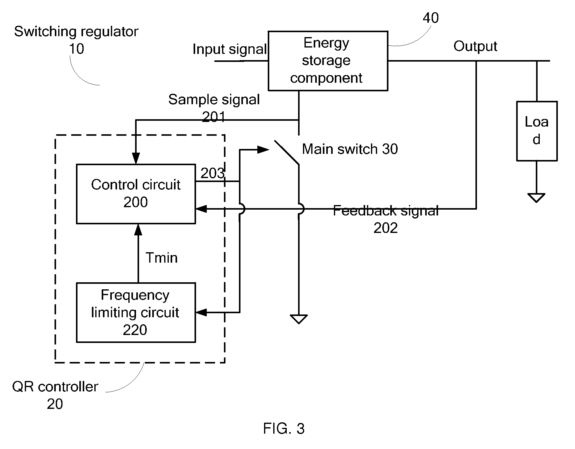
[0031]FIG. 3 shows a block diagram of a quasi-resonant controlled switching regulator 10 with frequency limitation in accordance with an embodiment of the present disclosure. The quasi-resonant controlled switching regulator 10 comprises: an energy storage component 40 configured to receive an input signal and to supply an output signal to a load; a main switch 30 coupled to the energy storage component 40, wherein the energy storage component 40 stores energy when the main switch 30 is turned ON, and transfers the stored energy to the lo...
PUM
 Abstract
Description
Claims
Application Information