Quasi-resonant controlled switching regulator and the method thereof

a switching regulator and quasi-resonant technology, applied in the direction of electric variable regulation, process and machine control, instruments, etc., can solve the problems of high switching loss and efficiency variation with load or input voltage, high switching frequency, and consequent emi (electromagnetic interference) problems

Active Publication Date: 2012-03-01
CHENGDU MONOLITHIC POWER SYST
View PDF4 Cites 23 Cited by
  • Summary
  • Abstract
  • Description
  • Claims
  • Application Information

AI Technical Summary

Benefits of technology

[0007]Under QR control, the lighter the load, the shorter the ON time period and OFF time period of the main switch. If the output voltage is fixed, the light load and the high input voltage may result in high switching frequency and the consequent EMI (electromagnetic interference) problem. The EMI may not only reduce the quality of the power network, but also influence electrical devices connected to or placed near the switching regulator. Therefore, the switching frequency should be limited, for example, to be lower than 150 kHz.
[0010]There are several methods of changing the minimum OFF time period Tlimit to avoid the switching frequency hopping. One method is to set two minimum OFF time periods. When one minimum OFF time period is close to the resonant valley, the system adopts the other minimum OFF time period to make sure there is enough distance between the minimum OFF time period and the resonant valley, so as to eliminate the risk of switching frequency hopping. The disadvantage of this method is that it is difficult to find two minimum OFF time periods suitable to a system under any conditions.
[0010]There are several methods of changing the minimum OFF time period Tlimit to avoid the switching frequency hopping. One method is to set two minimum OFF time periods. When one minimum OFF time period is close to the resonant valley, the system adopts the other minimum OFF time period to make sure there is enough distance between the minimum OFF time period and the resonant valley, so as to eliminate the risk of switching frequency hopping. The disadvantage of this method is that it is difficult to find two minimum OFF time periods suitable to a system under any conditions.

Problems solved by technology

Although fixed frequency control is more widely applied, it suffers from high switching loss and efficiency variation with load or input voltage.
If the output voltage is fixed, the light load and the high input voltage may result in high switching frequency and the consequent EMI (electromagnetic interference) problem.
The EMI may not only reduce the quality of the power network, but also influence electrical devices connected to or placed near the switching regulator.
However, this frequency limitation method may cause audible noise due to the frequency hopping.
The variation of the OFF time period of the main switch will cause the switching frequency to hop in several switching periods, which may generate low frequency audible noise.
The disadvantage of this method is that it is difficult to find two minimum OFF time periods suitable to a system under any conditions.

Method used


Image

  • Quasi-resonant controlled switching regulator and the method thereof
  • Quasi-resonant controlled switching regulator and the method thereof
  • Quasi-resonant controlled switching regulator and the method thereof

Examples


Embodiment Construction

[0030]In the present disclosure, numerous specific details are provided, such as examples of circuits, components, and methods, to provide a thorough understanding of embodiments of the disclosure. Persons of ordinary skill in the art will recognize, however, that the disclosure can be practiced without one or more of the specific details. In other instances, well-known details are not shown or described to avoid obscuring aspects of the disclosure.

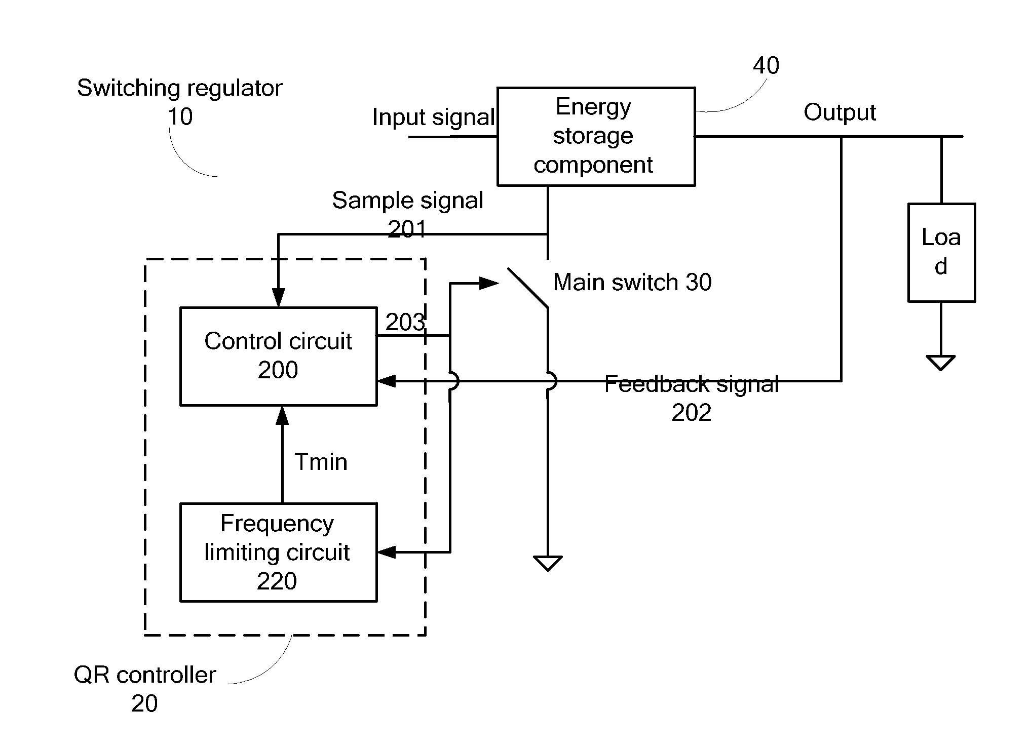
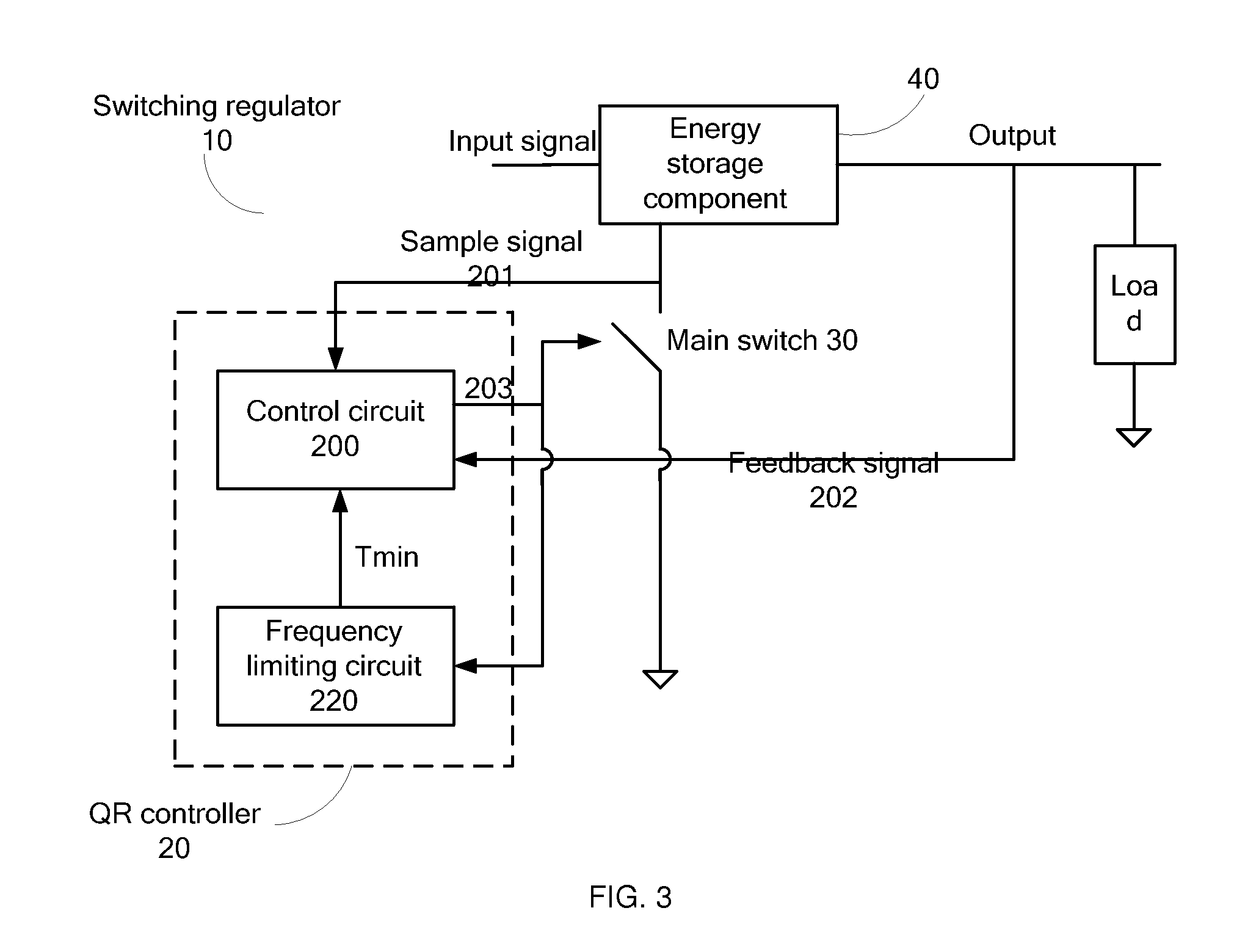
[0031]FIG. 3 shows a block diagram of a quasi-resonant controlled switching regulator 10 with frequency limitation in accordance with an embodiment of the present disclosure. The quasi-resonant controlled switching regulator 10 comprises: an energy storage component 40 configured to receive an input signal and to supply an output signal to a load; a main switch 30 coupled to the energy storage component 40, wherein the energy storage component 40 stores energy when the main switch 30 is turned ON, and transfers the stored energy to the lo...


PUM


Abstract

A frequency limitation method used in a quasi-resonant controlled switching regulator is disclosed. The switching frequency is limited by setting a minimum time period, such as a minimum switching period or a minimum OFF time period. The minimum time period is varying according to the difference between the minimum time period of the previous cycle and an offset value, so as to eliminate the audible noise caused by the frequency hopping when the minimum OFF time period is close to the valley of a quasi-resonant signal.

Description

CROSS-REFERENCE TO RELATED APPLICATIONS[0001]This application claims priority to and the benefit of Chinese patent application No. 201010270040.X, filed Aug. 27, 2010, which is incorporated herein by reference in its entirety.TECHNICAL FIELD[0002]The present disclosure relates generally to electrical circuits, and more particularly but not exclusively to switching regulators under quasi-resonant control.BACKGROUND OF THE INVENTION[0003]DC voltage sources are widely used as power supplies in many electronic devices. Generally, the DC voltage supplied by the DC voltage source is derived from an AC voltage. The AC voltage is rectified into an unregulated DC voltage by a rectifier firstly. Then the unregulated DC voltage is converted into a stable DC voltage as needed by the electronic devices.[0004]Generally, a switching regulator comprises an energy storage component and a main switch which is usually electronically coupled to the energy storage component. The main switch is turned ON...

Claims


Application Information

Patent Timeline
Patent Type & Authority Applications(United States)
IPC IPC(8): G05F1/10
CPCH02M3/156Y02B70/1491H02M2001/0058Y02B70/1425Y02B70/10H02M1/0058
Inventor LI, YIKEWANG, RUILI, EN
Owner CHENGDU MONOLITHIC POWER SYST
Why Eureka
Try Eureka