Antireflection film, polarizing plate and image display device

a technology of polarizing plate and anti-reflection film, which is applied in the direction of polarizing elements, instruments, transportation and packaging, etc., can solve the problems of uneven reflected color, difficult to form optical interference thin films in thicknesses of 50 to 150 mm with good precision, and inconvenient mass production methods, etc., to reduce the difference in reflected color, enhance productivity, and less change in reflected color

Active Publication Date: 2014-04-08
FUJIFILM CORP
View PDF11 Cites 27 Cited by
  • Summary
  • Abstract
  • Description
  • Claims
  • Application Information

AI Technical Summary

Benefits of technology

[0012]The present invention provides an antireflection film satisfying the reduction of reflection, causing less change in the reflected color due to fluctuation in the thickness of each layer of the antireflection film, and enabling to enhance the productivity by decreasing the difference in reflected color among finished products or hardly allowing the coating unevenness or streak to be perceived. The present invention further provides an antireflection film assured of good neutral property and less projection of outside light. The present invention still further provides a polarizing plate and a liquid crystal display device each using the antireflection film and having the above-described effects.
[0013]As a result of intensive studies to solve those problems, the present inventors have found that the above-described objects can be achieved by setting the refractive index and thickness of each layer to fall in the range of a specific relational formula and also found that by virtue of setting the refractive index and thickness of each layer to fall in a specific range, when an inorganic fine particle is further incorporated into the low refractive index layer, a remarkable effect is obtained. The present invention has been accomplished based on these findings.

Problems solved by technology

However, the method of forming a transparent thin film of metal oxide by vapor deposition or sputtering is not suited for mass production because of its low productivity, and a formation method by a wet film-forming method with high productivity, particularly, a coating system, is proposed.
For example, in the wet coating, although this may vary depending on the coating system, it is very difficult to form an optical interference thin film in thickness of approximately from 50 to 150 mm with good precision.
Usually, thickness unevenness of 5 to 10 nm is generated and there arises a problem that reflected color corresponding to the unevenness is observed or a failure such as coating streak is liable to be highly visible.

Method used


Image

  • Antireflection film, polarizing plate and image display device
  • Antireflection film, polarizing plate and image display device
  • Antireflection film, polarizing plate and image display device

Examples


example 1

Production of Antireflection Film

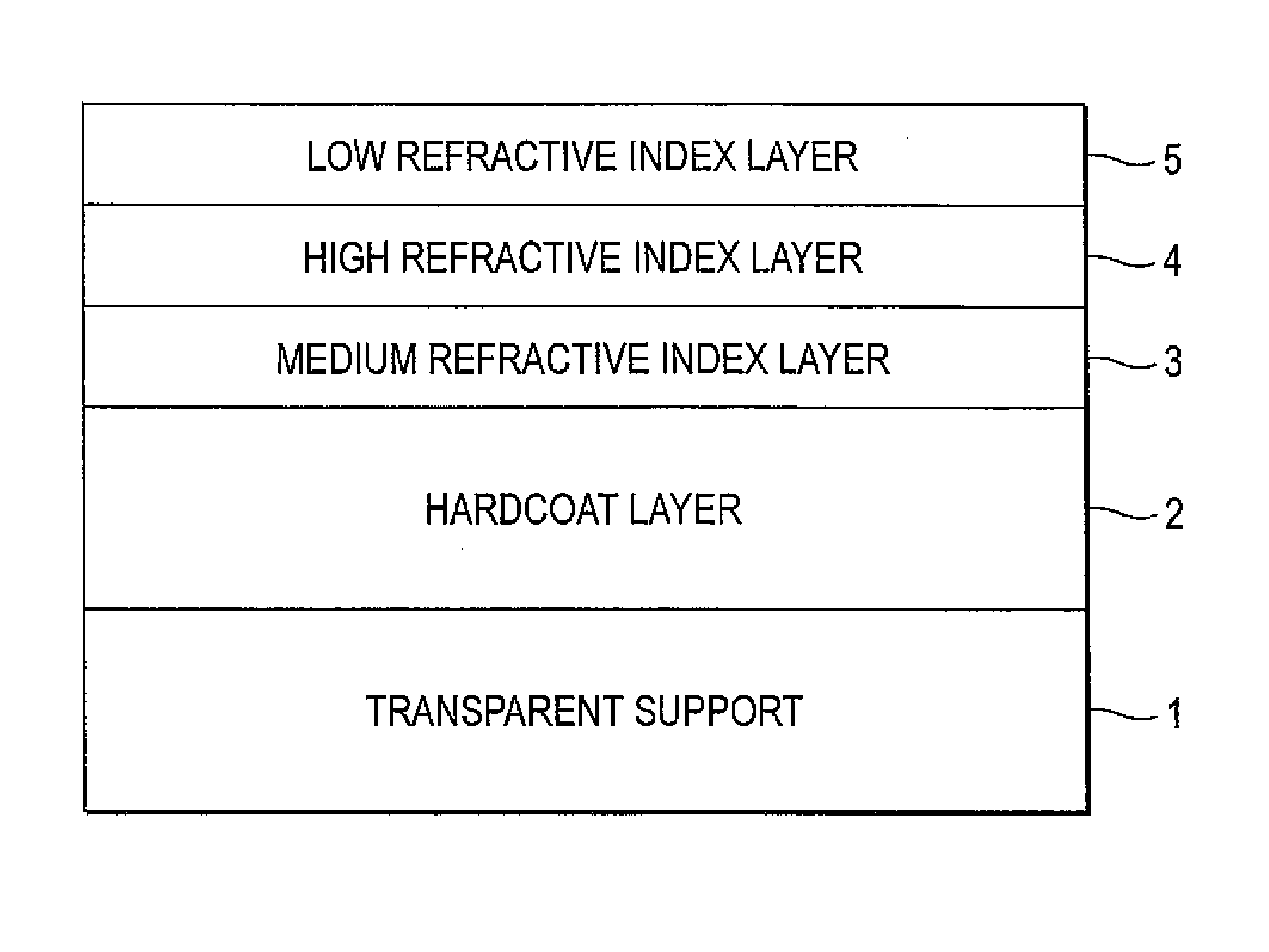
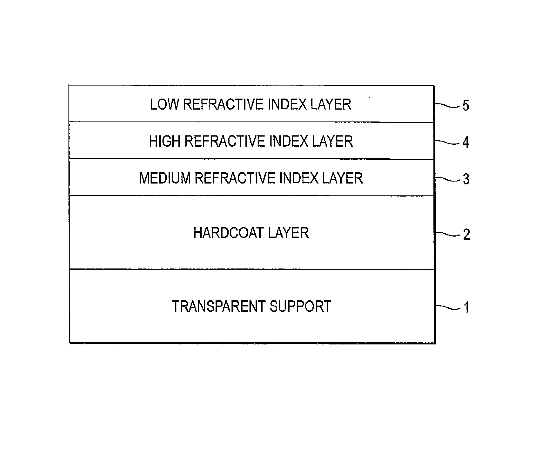
[0437]Preparation of the coating solution for the formation of each layer and formation of each layer are performed as follows to produce Antireflection Film Nos. 1 to 17.

(Preparation of Coating Solution a for Hardcoat Layer)

[0438]The composition shown below is charged into a mixing tank and the resulting solution is stirred to prepare a coating solution for hardcoat layer.

[0439]270.0 Parts by mass of poly(glycidyl methacrylate) having a mass average molecular weight of 15,000, 730.0 parts by mass of methyl ethyl ketone, 500.0 parts by mass of cyclohexanone and 50.0 parts by mass of a photopolymerization initiator (Irgacure 184, produced by Ciba Specialty Chemicals Corp.) are added to 750.0 parts by mass of trimethylolpropane triacrylate (VISCOAT #295, produced by Osaka Organic Chemical Industry Ltd.), and the resulting mixture is stirred and filtered through a polypropylene-made filter having a pore size of 0.4 μm to prepare Coating Solution A for H...

example 2

[0486]Seventeen antireflection films produced in Example 1 each is dipped in an aqueous 2.0 mol / L NaOH aqueous solution at 55° C. for 2 minutes to saponify the triacetyl cellulose surface which is the back surface of the film, and a 80 μm-thick triacetyl cellulose film (TAC-TD80U, produced by Fujifilm Corp.) is saponified under the same conditions. A polarizing film is produced by adsorbing iodine to a stretched polyvinyl alcohol film, and one side of the polarizing film is laminated to the saponified antireflection film of Example 1 by using a polyvinyl alcohol-based adhesive such that the transparent support (triacetyl cellulose) side of the antireflection film becomes the polarizing film side. A viewing angle-enlarging film having an optically compensatory layer, “Wide View Film SA12B” {produced by Fujifilm Corp.} is saponified and laminated to another side of the polarizing film by using a polyvinyl alcohol-based adhesive. In this way, a polarizing plate is produced. In place of...

example 3

[0499]The samples of Example 1 each is laminated to the outermost surface on the viewing side of OCB-type liquid crystal display devices described in Examples 10, 15, 18 and 19 of JP-A-2000-154261 by using a polyvinyl alcohol-based adhesive. In Sample Nos. 1 to 4 of the present invention, a liquid crystal display device with very high display quality, where the projection of scene in back is very little, the color tint of reflection is not bothersome, the bright-room contrast is high, the viewing angle in the up / down and right / left directions is very wide, the visibility is remarkably excellent, and the color tint of reflection is not annoying, is obtained.


PUM

PropertyMeasurementUnit
thicknessaaaaaaaaaa
thicknessaaaaaaaaaa
refractive indexaaaaaaaaaa

Abstract

An antireflection film includes, in a following order, a transparent substrate film; a medium refractive index layer; a high refractive index layer; and a low refractive index layer, wherein the medium refractive index layer is (A) a medium refractive index layer having a refractive index of 1.60 to 1.64 at a wavelength of 550 nm and a thickness of 55.0 to 65.0 nm, the high refractive index layer is (B) a high refractive index layer having a refractive index of 1.70 to 1.74 at a wavelength of 550 nm and a thickness of 105.0 to 115.0 nm, and the low refractive index layer is (C) a low refractive index layer having a refractive index of 1.32 to 1.37 at a wavelength of 550 nm and a thickness of 85.0 to 95.0 nm.

Description

BACKGROUND OF THE INVENTION[0001]1. Field of the Invention[0002]The present invention relates to an antireflection film, a polarizing plate using the antireflection film, and an image display device using the antireflection film or polarizing plate. More specifically, the present invention relates to an antireflection film enabling to prevent the visibility at a high level from worsening due to projection of reflected light, causing less reduction in the display quality, hardly allowing point defects or scratches to be perceived, and having good durability.[0003]2. Description of the Related Art[0004]In various image display devices such as liquid crystal display device (LCD), plasma display panel (PDP), electroluminescent display (ELD) and cathode ray tube display device (CRT), an antireflection film is disposed on the display surface so as to prevent the reduction in contrast due to reflection of outside light or projection of figure. Accordingly, the antireflection film is requir...

Claims


Application Information

Patent Timeline
Patent Type & Authority Patents(United States)
IPC IPC(8): C09K19/00G02B1/11B32B7/02G02B1/111G02B1/14G02B1/16G02B5/30G02F1/1335
CPCG02B1/111Y10T428/31612Y10T428/265Y10T428/259Y10T428/24967Y10T428/10Y10T428/31645Y10T428/1036C09K2323/00C09K2323/03G02F1/133502H01J2211/442
Inventor ASAKURA, TETSUYASUZUKI, TAKATO
Owner FUJIFILM CORP
Why Eureka
Try Eureka