Method of manufacturing a stator component

a technology of stator components and manufacturing methods, applied in non-electric welding apparatuses, machines/engines, electron beam welding apparatuses, etc., can solve the problems of large and complicated casting facilities, time-consuming and expensive operations, etc., and achieve less complex casting facilities, less complicated design, and efficient welding processes

Active Publication Date: 2008-06-24
GKN AEROSPACE SWEDEN AB
View PDF9 Cites 32 Cited by
  • Summary
  • Abstract
  • Description
  • Claims
  • Application Information

AI Technical Summary

Benefits of technology

[0012]As the sectors are cast individually, there are certain advantages in relation to casting the whole stator component in a single step. One advantage is that in the event of a fault or a defect, it is not necessary to reject a whole stator component, but only one sector. An additional advantage is that the casting is less complex, with smaller parts of a less complicated design.
[0013]According to an aspect of the invention, the surface of each of the sectors that is intended to be welded is continuous. In other words, the welding surface has no interruptions or sudden changes in direction. By this means, it is possible to have an efficient welding process that provides a highly durable welded joint. In addition, the surface of each of the sectors that is intended to be welded is essentially of the same thickness in cross-section over the length of the whole surface. By this means, there is considerably less need to change the welding parameters during the welding process.
[0014]According to another aspect of the invention, other parts of the sector adjacent to the surface that is intended to be welded are set back slightly in the direction of the circumference relative to the welding surface in order not to interfere with the weld path. This applies, in particular, when the sectors are cast in such a shape that they each have at least one rib that extends in the direction of the circumference and projects in an axial direction. The sector is then cast in such a shape that the rib extends in such a way that there is a gap in the direction of the circumference between the end of the rib and the edge of the sector. This makes it possible to join the sectors together in a simple way after the sectors have been placed adjacent to each other. After the sectors have been placed adjacent to each other in the direction of the circumference, the sectors are thus joined by welding together the sectors' adjacent edges between the ends of the ribs in a radial direction.

Problems solved by technology

This is a time-consuming and expensive operation.
This requires, however, a large and very complicated casting facility.

Method used


Image

  • Method of manufacturing a stator component
  • Method of manufacturing a stator component
  • Method of manufacturing a stator component

Examples


Embodiment Construction

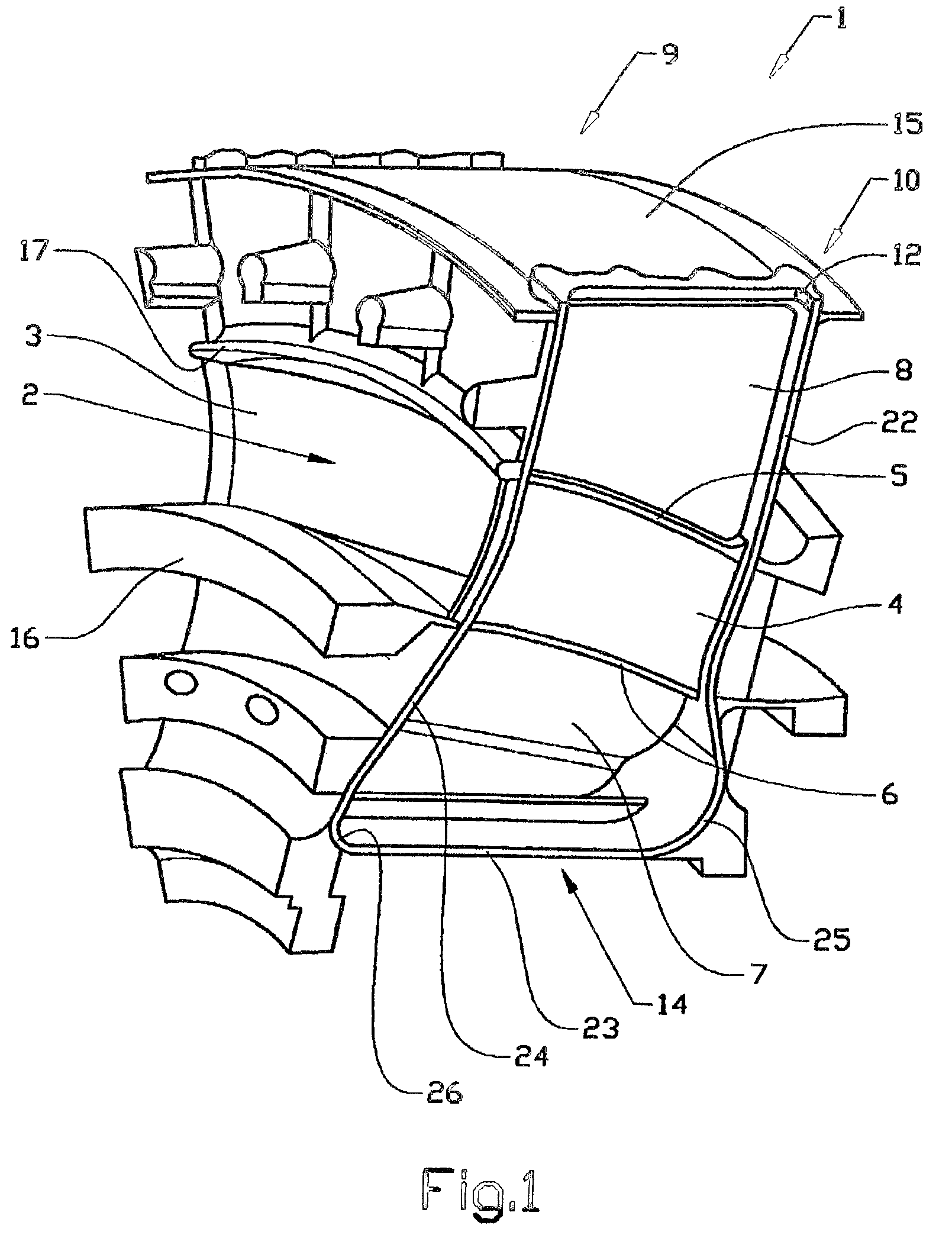
[0020]FIG. 1 shows a cast sector 1 in a perspective view.

[0021]The sector 1 has a gas duct 2 that goes right through, principally in an axial direction. It is also possible to have one or more gas ducts in a radial direction for compressor flow (not shown), and also in certain cases fan flow.

[0022]The sector 1 has been cast with wall elements 4, 5, 6, 7, 8 that form a continuous structure in the radial direction in order to transfer loads. In the illustrated embodiment, the sector 1 comprises a first wall element 3 and a second wall element 4, which extend in the intended radial direction of the stator component and are arranged at a distance from each other in order to define between them the gas duct 2 in the direction of the circumference of the stator component.

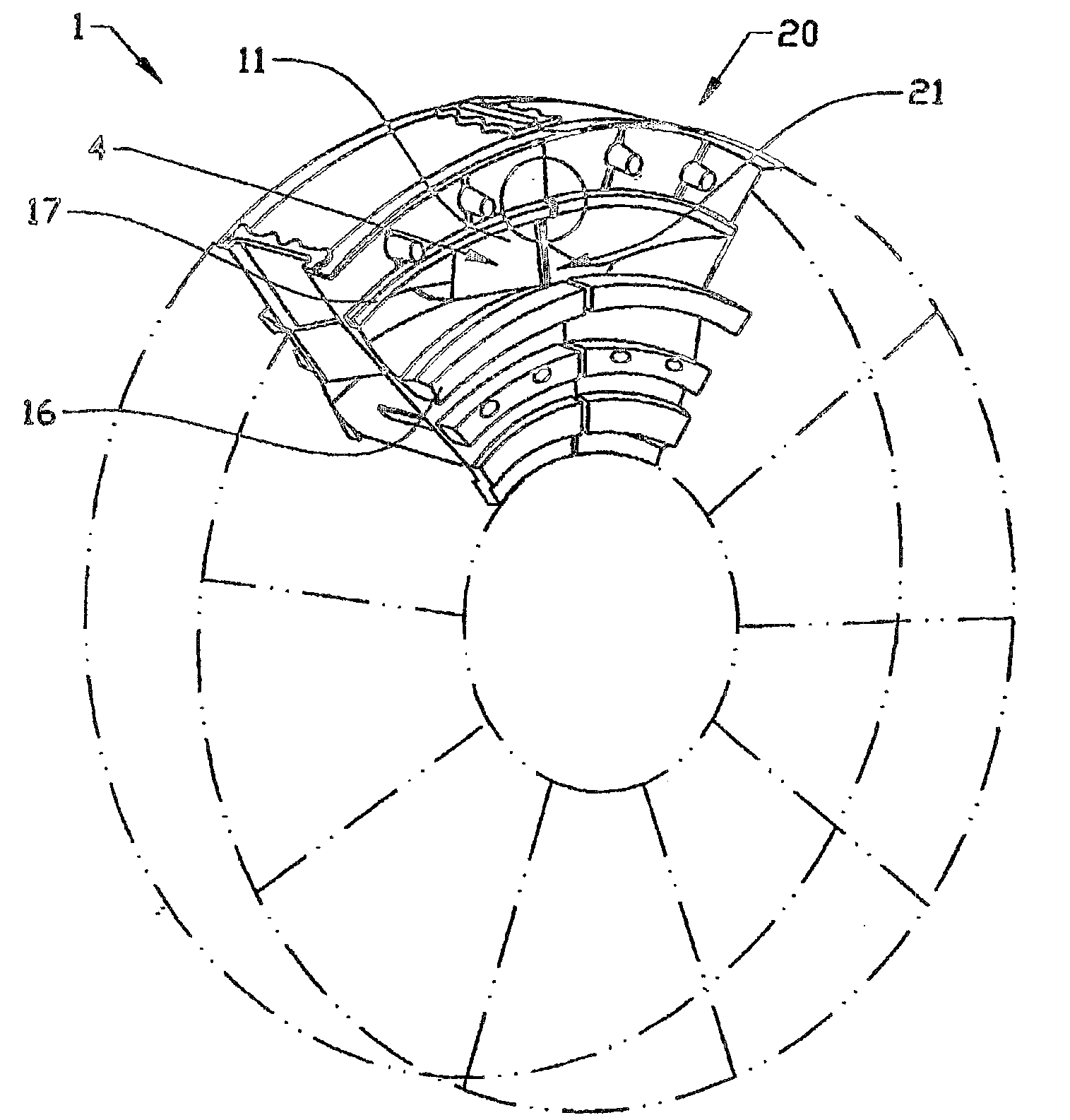
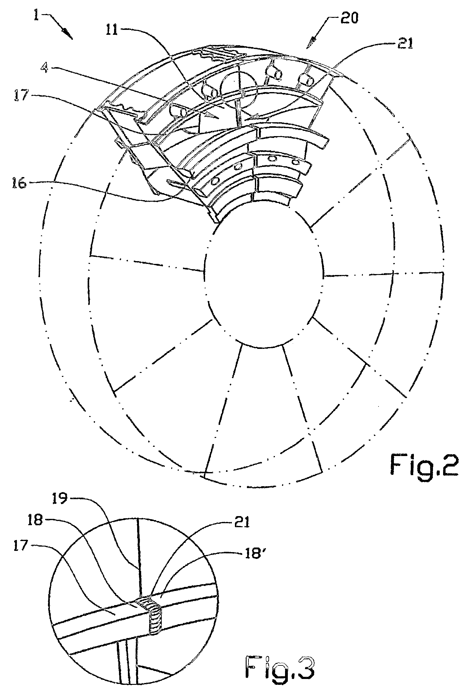
[0023]When two sectors are joined together, the continuous wall structure 4, 5, 6, 7, 8 together with a corresponding wall structure 21 of an adjacent sector form a device 11 extending in the radial direction of the compo...


PUM

PropertyMeasurementUnit
circumferenceaaaaaaaaaa
distanceaaaaaaaaaa
thicknessaaaaaaaaaa

Abstract

The invention relates to a method for manufacturing a stator component that is intended in operation to guide a gas flow and to transfer loads. The component is constructed of at least two sectors in the direction of its circumference. The sectors are cast in separate pieces, positioned adjacent to each other and joined together by welding.

Description

[0001]The present application is a continuation of International Application PCT / SE2004 / 000387, filed Mar. 16, 2004.BACKGROUND AND SUMMARY[0002]The present invention relates to a method for manufacturing a stator component that is intended in operation to guide a gas flow and to transfer loads.[0003]The stator component can, for example, be utilized in a gas turbine and, in particular, in a jet engine.[0004]By jet engine is meant various types of engine that take in air at a relatively low speed, heat it up by combustion and expel it at a much higher speed. The term jet engine includes, for example, turbo-jet engines and turbo-fan engines.[0005]Such a stator component that comprises an outer and an inner ring with wall elements arranged between the rings, can be arranged with the aim of primarily being load-transferring in a radial and axial, and also in a tangential, direction. The wall elements can, for example, form hollow blades, which are usually such a shape that they present ...

Claims


Application Information

Patent Timeline
Patent Type & Authority Patents(United States)
IPC IPC(8): B21K25/00H02K15/00B23K15/00B23K26/32B23P15/04F01D9/04F01D25/24
CPCB23K15/0093B23P15/04F01D9/041F01D25/246B23K2201/001Y10T29/49009F05D2240/40F05D2230/232Y10T29/49323Y10T29/49988Y02T50/673B23K2101/001Y02T50/60
Inventor LUNDGREN, JAN
Owner GKN AEROSPACE SWEDEN AB
Why Eureka
Try Eureka