Device and method to produce helical coils from a filament

a technology of helical coils and filaments, which is applied in the direction of dough shaping, dough sheets/rolling machines/rolling pins, cocoa, etc., can solve the problem of complex design of the prior-art device, and achieve the effect of less complicated design

Active Publication Date: 2009-02-24
KUGLER WOMAKO
View PDF5 Cites 0 Cited by
  • Summary
  • Abstract
  • Description
  • Claims
  • Application Information

AI Technical Summary

Benefits of technology

[0004]It is the objective of the present invention to improve a device and a method of the type mentioned above in such a manner as to allow a less complicated design.
[0007]The invention allows the production of helical coils of nearly unlimited length using a winding spindle of limited length. This allows a particularly compact design of the device.
[0008]The fact that the invention provides for a downstream pressing device makes it possible to use a comparatively short version of the rather expensive filament-shaping device, which then constitutes only a comparatively small constructional unit, while the required design of the pressing device is comparatively uncomplicated. In this manner it becomes possible to reduce the expense of the overall design of the device in comparison to the state of technology.
[0017]A particularly favoured embodiment of the invention is characterized in that at least one pressure element is realized as a rotatable roller, with an axis of rotation that preferably extends predominantly in parallel to the axis of rotation of the winding spindle. The rotatable roller should be able to rotate freely; no drive is required. This ensures that the friction between the pressure element and the filament is lower than that between the filament and the winding spindle, allowing the creation of the friction lock with the winding spindle that is necessary to generate movement.
[0019]A further especially preferred embodiment is characterized in that the winding spindle comprises anchoring means to secure the filament to be wound up, and is movable along the axial direction between a first position, in which the anchoring means is located in the upstream—as seen along the feed direction of the filament to be wound onto the winding spindle—region of the filament-shaping device and a second position, in which the anchoring means is located in the region of the pressing device. This embodiment allows a particularly uncomplicated set-up of the device for a subsequent continuous production of a helical coil by attaching the beginning of the filament to the winding spindle with the help of the anchoring means and by subsequently subjecting the winding spindle to a combined advance and rotational movement, in order to introduce the filament into the shaping device in a carefully directed manner and to carry it through the shaping device, whereupon the continuous manufacturing process commences. It is practical if the anchoring means in this embodiment is a hole formed in the casing of the winding spindle, into which the filament is inserted to fasten it to the winding spindle.

Problems solved by technology

The overall design of this prior-art device is quite complex, in particular due to the fact that the filament-cooling device is realized as a pitch guide tube.

Method used


Image

  • Device and method to produce helical coils from a filament
  • Device and method to produce helical coils from a filament
  • Device and method to produce helical coils from a filament

Examples


Embodiment Construction

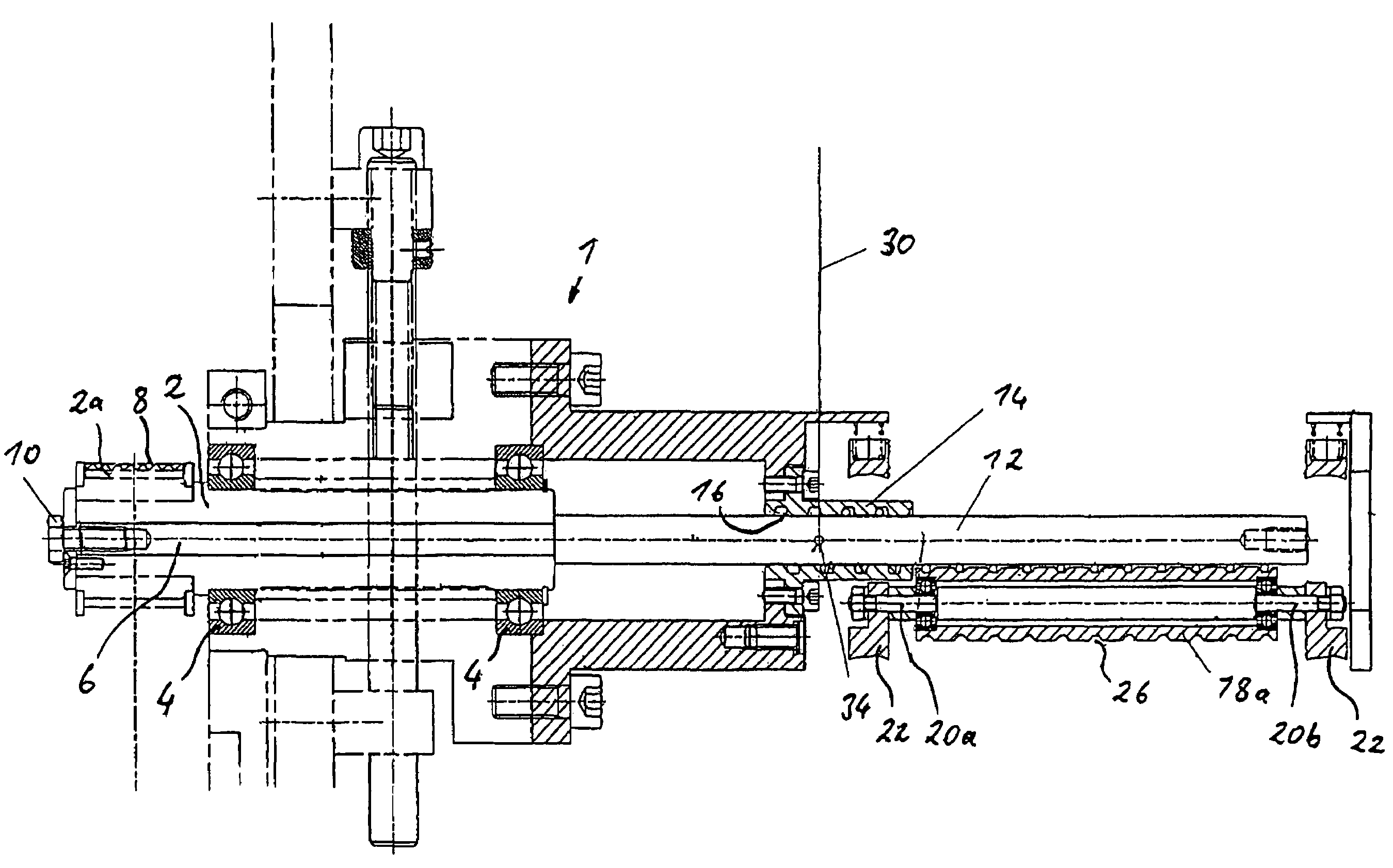
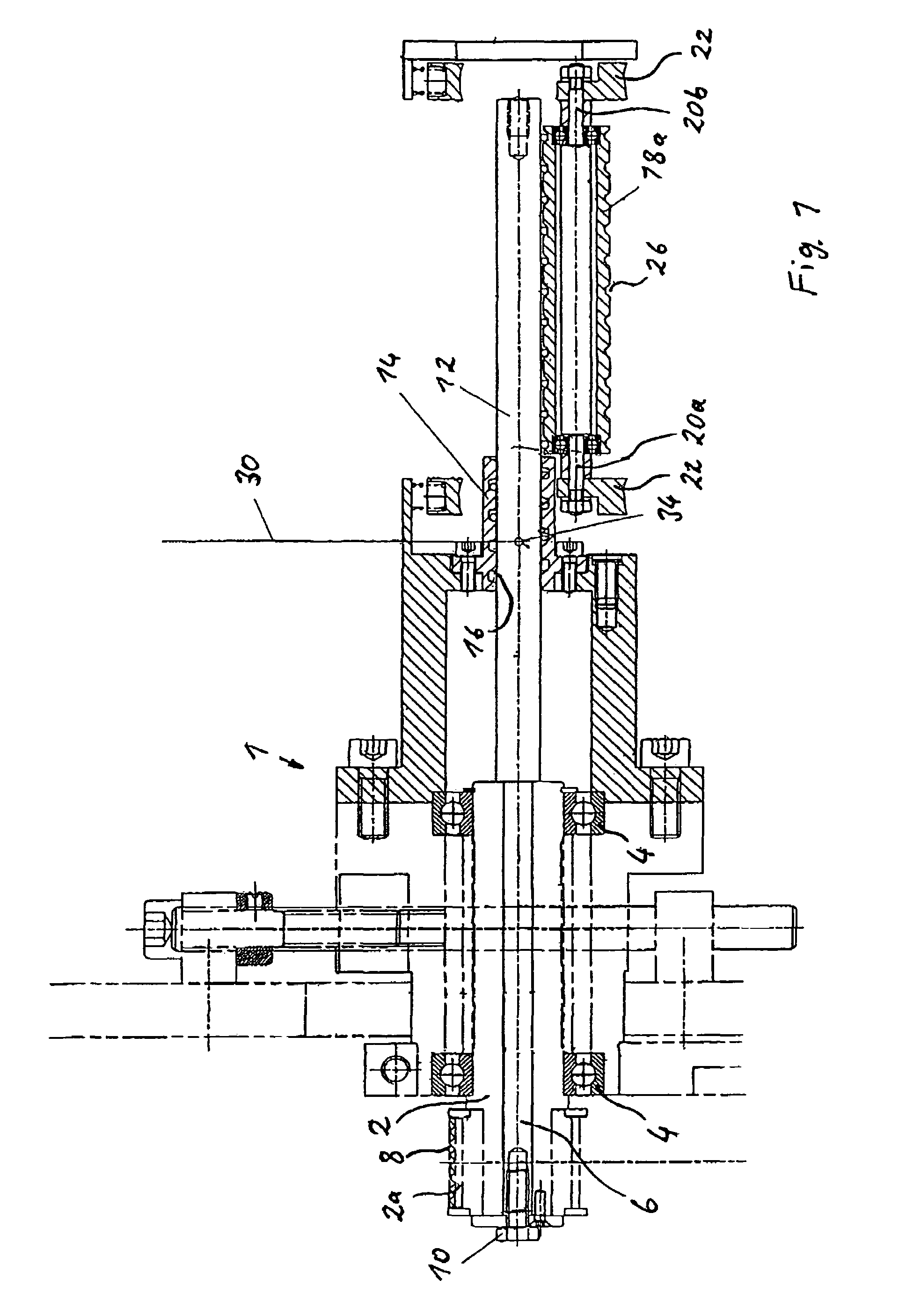
[0034]As discernable in FIG. 1, the illustrated device comprises a rigid housing component 1, in which a hollow shaft 2 is supported in a rotatable manner by means of ball bearings 4 and is secured against a longitudinal movement in a manner known in the art. A pin 6 is arranged concentrically within the hollow shaft 2. The exposed exterior end section 2a of the hollow shaft 2 is realized as co-axial roller, over which runs a driving belt 8, which is driven by a driving device that is not shown. While the hollow shaft 2 is stationary, the interior pin 6 is fundamentally free to rotate with respect to the surrounding hollow shaft 2 and is free to move in the axial direction. However, a link between the pin 6 and the hollow shaft 2 that is rigid with respect to rotation and displacement can be created with the help of a screw connection 10 at the exposed outer end.

[0035]On the opposite side, a winding spindle 12 is arranged coaxially at the pin 6. The winding spindle 12 usually is con...


PUM

PropertyMeasurementUnit
pressureaaaaaaaaaa
angular distanceaaaaaaaaaa
frictionaaaaaaaaaa

Abstract

Presented are a device and a method to produce helical coils from a filament, preferably consisting of plastic. A rotatable winding spindle and an associated filament-shaping device are provided to wind up the filament in a helical pattern, whereby the winding spindle extends beyond the filament-shaping device in the feed direction of the filament to be wound up. Viewed in the feed direction of the filament to be wound onto the winding spindle, a pressing device is provided downstream of the filament-shaping device that presses the filament against the winding spindle and is designed to generate a predominantly adequate friction contact between the filament and the winding spindle so that the rotation of the winding spindle essentially takes along the filament into the winding direction.

Description

CROSS-REFERENCE TO RELATED APPLICATION[0001]This application claims the priority of German Patent Application No. 10 2004 021 776.9-16, filed on Apr. 30, 2004, the subject matter of which is incorporated herein by reference. The disclosure of all U.S. patents and patent applications mentioned below are also incorporated herein by reference.BACKGROUND OF THE INVENTION[0002]The invention relates to a device to produce helical coils from a filament, preferably of plastic, comprising a rotatable and preferably smooth winding spindle and an associated filament-shaping device to wind the filament onto the winding spindle in a helical pattern, whereby the winding spindle extends—as seen along the feed direction of the filament to be wound upon it—beyond the filament-shaping device. The invention further relates to a method to produce a helical coil from a filament—preferably consisting of plastic—preferably using a device of the type mentioned above.[0003]A device and method of this type a...

Claims


Application Information

Patent Timeline
Patent Type & Authority Patents(United States)
IPC IPC(8): B65H54/00B65H55/00B21F3/02B29C53/12B29C53/56B65H54/28B65H81/06
CPCB29C53/12
Inventor LEHMANN, HARTMUTVIETH, GUNNAR
Owner KUGLER WOMAKO
Why Eureka
Try Eureka