Frequency-locking device and frequency-locking method thereof

a frequency-locking device and frequency-locking technology, applied in the direction of digital transmission, pulse automatic control, electrical apparatus, etc., can solve the problems of increasing the manufacturing cost and electricity consumption of the whole device, increasing the memory cost of the frequency-locking device b>10/, and achieving the precise frequency-locking effect. , the effect of reducing the complexity of design

Inactive Publication Date: 2009-09-17
SONIX TECH
View PDF10 Cites 3 Cited by
  • Summary
  • Abstract
  • Description
  • Claims
  • Application Information

AI Technical Summary

Benefits of technology

[0011]In view of the above-mentioned problems, the present invention provides a frequency-locking device with advantages of low-producing cost, less-complicated design, and low electricity consumption. The frequency-locking device according to one embodiment of the invention includes a digitally-controlled oscillator and a comparing unit. The digitally-controlled oscillator is used to generate an output frequency signal. The comparing unit receives a KEEP ALIVE signal or a start of a frame and the output frequency signal, and then compares the KEEP ALIVE signal or the start of a frame with the output frequency signal to generate a calibration signal. The digitally-controlled oscillator performs an adjustment according to the calibration signal to lock the frequency of the output frequency signal to a specific or predetermined frequency for data communication.
[0013]In the embodiments of the invention, the frequency-locking device and method thereof takes a KEEP ALIVE signal or a start of a frame as a reference for the calibration signal rather than takes a more complicated packet data as references for correction, and which shows a more precise frequency-locking effect. Also, the present invention does not need any look-up table. Consequently, the circuit design for the present invention becomes easier and the effect of reduced complexity in design, lowered production cost, and lowered electricity consumption can be obtained.

Problems solved by technology

However, the way of generating the correction signal FACTOR according to the data packets of the universal serial bus makes the actual design and operation of circuit more complicated and defective.
Besides, the great amount of memory space occupied by the look-up table inside the frequency-locking device 10 increases the memory cost for the frequency-locking device 10.
The above-mentioned problems highly raise the manufacturing cost and the electricity consumption of the whole device.

Method used


Image

  • Frequency-locking device and frequency-locking method thereof
  • Frequency-locking device and frequency-locking method thereof
  • Frequency-locking device and frequency-locking method thereof

Examples


Embodiment Construction

[0023]Reference will now be made to the drawings in which the various elements of the present invention will be given numerical designations and in which the invention will be discussed so as to enable one skilled in the art to make and use the invention.

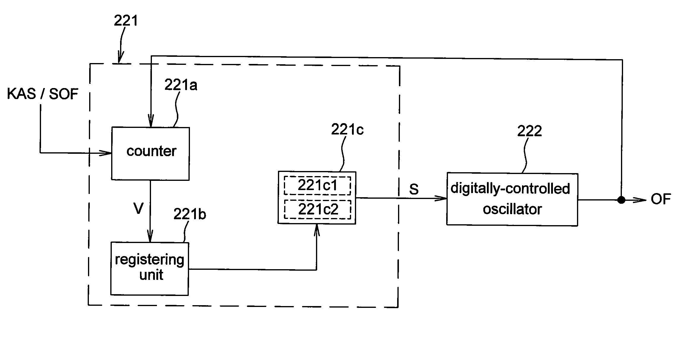
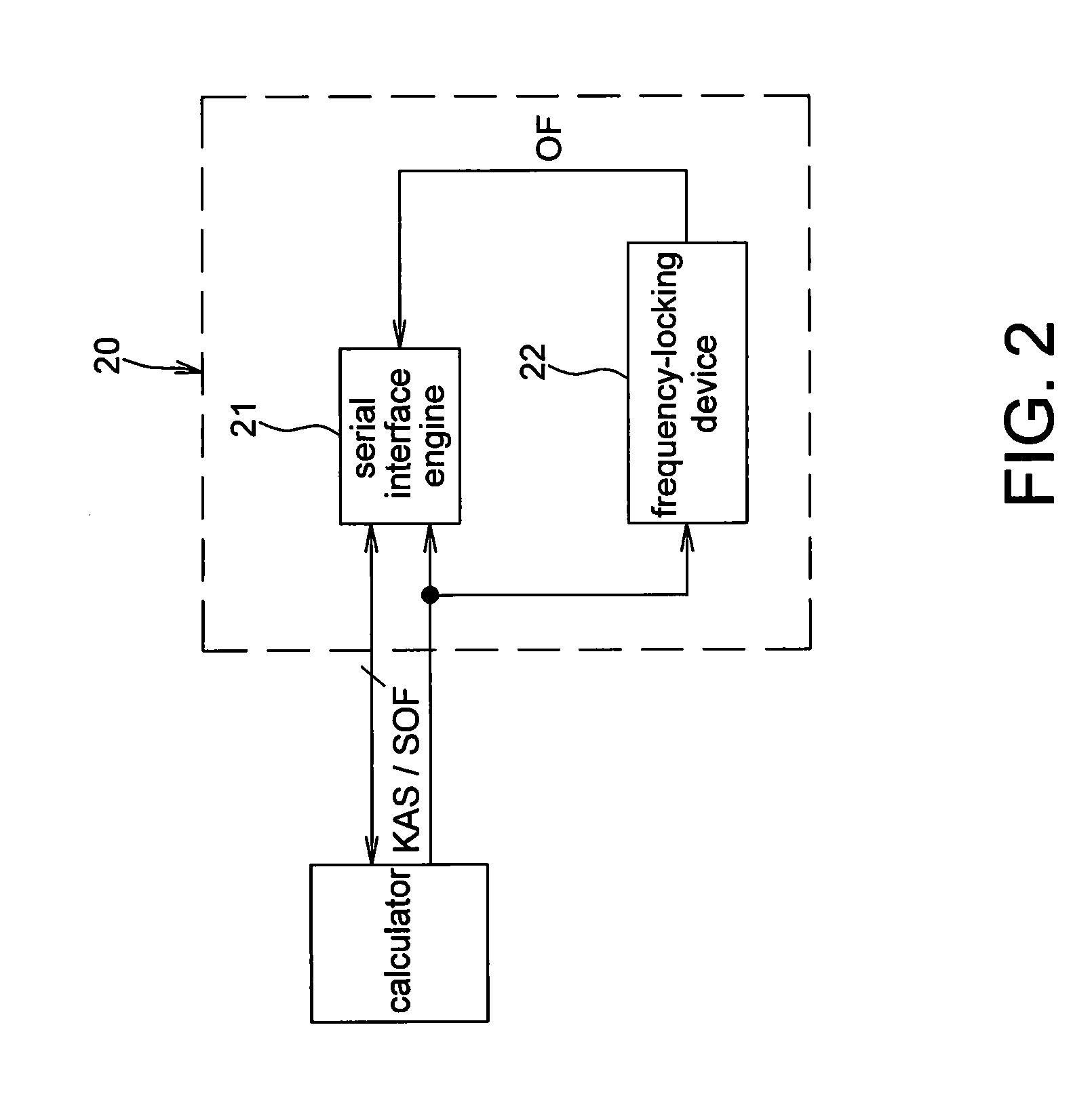
[0024]Referring to FIG. 2, the universal serial bus device 20 according to one embodiment of the present invention receives the KEEP ALIVE signal KAS or the start of a frame SOF generated by a calculator such as a computer, and has data communication with the calculator. The universal serial bus device 20 includes a serial interface engine (SIE) 21 and a frequency-locking device 22. Both the serial interface engine 21 and the frequency-locking device 22 receive a KEEP ALIVE signal KAS or a start of a frame SOF, and the frequency-locking device 22 generates an output frequency signal OF according to the KEEP ALIVE signal KAS or the start of a frame SOF. The frequency of the output frequency signal OF is locked to a specific or a pred...


PUM


Abstract

A frequency-locking device including a digitally-controlled oscillator (DCO) and a comparing unit is disclosed. The DCO is used for generating an output frequency signal. The comparing unit receives a Keep Alive signal or a start of a frame (SOF) from a universal serial bus (USB) and the output frequency signal, and compares the Keep Alive signal or the start of a frame (SOF) with the output frequency signal to generate a calibration signal. Then, the DCO adjusts the frequency of the output frequency signal according to the calibration signal to meet the USB specification for data communication.

Description

CROSS REFERENCES TO RELATED APPLICATIONS[0001]This application is a continuation-in-part of U.S. patent application Ser. No. 11 / 706,199, filed Feb. 15, 2007, now pending.BACKGROUND OF THE INVENTION[0002]1. Field of the Invention[0003]The present invention relates to a frequency-locking device and, more particularly, to a frequency-locking device applied to universal serial bus.[0004]2. Description of the Related Art[0005]As shown in FIG. 1, a frequency-locking device 10 applied to data communication of a universal serial bus was disclosed in U.S. Pat. No. 6,297,705. When the frequency-locking device 10 is used, the output clock of an oscillator 142 is locked to the rate of incoming data stream which input to the frequency-locking device 10. The object of this technology is to precisely lock the output clock of the oscillator 142 to the rate of the incoming data stream without utilizing any external precision timing element such as a crystal or a resonator, and provide multiple tunin...

Claims


Application Information

Patent Timeline
Patent Type & Authority Applications(United States)
IPC IPC(8): H03L7/099
CPCH03L7/085H03L7/0991H04L7/046H04L7/0004H04L7/033H03L7/181
Inventor LIAO, CHIH-MINGCHEN, CHIA-CHANGCHEN, MIN-YI
Owner SONIX TECH
Why Eureka
Try Eureka