Treatment installation and method for treating workpieces

Pending Publication Date: 2019-07-18
EISENMANN GMBH
View PDF0 Cites 3 Cited by
  • Summary
  • Abstract
  • Description
  • Claims
  • Application Information

AI Technical Summary

Benefits of technology

The invention provides a gas barrier between a treatment tunnel and a driving area to prevent the transfer of atmosphere. This design reduces the complexity of any necessary lock technology and allows the gas compartment to remain small. The gas compartment is connected to the treatment tunnel and the driving area through separate passages, ensuring that the gas always flows around the coupling device. A pressure can be developed in the gas compartment to prevent unwanted atmospheres from entering. The gas supply device includes a conditioning device to match the gas to the atmosphere in the treatment tunnel. The gas compartment is connected to the treatment tunnel and the driving area through separate passages, and a flow guiding device is used to reduce the flow section of the gas barrier.

Problems solved by technology

This corrodes the conveyor system, however.
However, the considerable disadvantage here is that impurities can be introduced from the driving area into the treatment tunnel.
Such impurities can, in particular, involve abrasion or lubricants from the components of the conveyor system in the driving area.
However, the treatment of the workpieces in the treatment tunnel can be badly disrupted by such impurities.
However, a comparatively large volume of gas has to be moved.
In addition, at the ends of the driving area locks have to be provided in order to maintain the pressure in the driving area including during entry and exit by the trolleys; however, simply due to the necessary cross section, construction of these locks is complicated.

Method used


Image

  • Treatment installation and method for treating workpieces
  • Treatment installation and method for treating workpieces
  • Treatment installation and method for treating workpieces

Examples


Embodiment Construction

[0051]While this invention is susceptible to embodiments in many different forms, there is described in detail herein, preferred embodiments of the invention with the understanding that the present disclosures are to be considered as exemplifications of the principles of the invention and are not intended to limit the broad aspects of the invention to the embodiments illustrated.

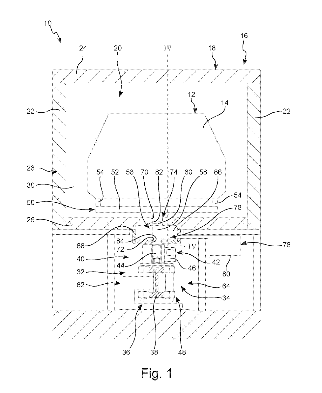
[0052]The figures schematically illustrate a treatment installation designated in its entirety as 10 for the treatment of workpieces 12 which, by way of example, are shown as vehicle bodies 14.

[0053]The treatment installation 10 comprises a treatment device 16 with a housing 18, delimiting a treatment chamber, configured as a treatment tunnel 20 and comprising two tunnel walls in the form of side walls 22 and two further tunnel walls in the form of a ceiling 24 and a tunnel floor 26. In a preferred exemplary embodiment, the treatment device 16 is a dryer 28, in which the treatment tunnel 20 defines a drying ...


PUM


Abstract

A treatment installation for treating workpieces, in particular for coating and / or drying of vehicle bodies, having a treatment device with a housing, in which a treatment tunnel is accommodated. A conveyor system having a plurality of trolleys which can convey the workpieces through the treatment tunnel, wherein each of the trolleys has a chassis and a securing device for at least one workpiece which are coupled together by a coupling device. Outside the treatment tunnel a guidance zone with a driving area for the chassis is present. In the guidance zone a gas compartment is configured, arranged between the driving area and the treatment tunnel and delimited by a separate housing. A gas supply device is present which can supply the gas compartment with a gas, such that in the gas compartment a gas barrier is created between the treatment tunnel and the driving area.

Description

RELATED APPLICATIONS[0001]The present application claims priority to German Application No. 10 2018 100 719.1 filed Jan. 15, 2018 and German Application No. 10 2018 103 454.7 filed Feb. 15, 2018—the contents of both of which are fully incorporated herein by reference.FIELD OF THE INVENTION[0002]The invention relates to a treatment installation for treating workpieces, in particular for coating and / or drying of vehicle bodies, with[0003]a) a treatment device with a housing, in which a treatment tunnel is accommodated;[0004]b) a conveyor system, comprising a plurality of trolleys, by means of which the workpieces are transportable through the treatment tunnel, wherein each trolley comprises a chassis and a securing device for at least one workpiece, which are coupled together by means of a coupling device;wherein[0005]c) outside the treatment tunnel a guidance zone with a driving area for the chassis is present.[0006]The invention also relates to a method for treating workpieces, in p...

Claims


Application Information

Patent Timeline
IPC IPC(8): B05B12/18B05B15/00
CPCB05B12/18B05B15/00B05D3/0406B05B16/60B05B13/0221B05B13/0285B60S3/002F26B2210/12B05D7/14B05D1/02B05D3/02
Inventor SCHULZE, HERBERT
Owner EISENMANN GMBH
Why Eureka
Try Eureka