Check patentability & draft patents in minutes with Patsnap Eureka AI!

Chain conveyor apparatus

a chain conveyor and chain conveyor technology, applied in the direction of conveyor parts, non-mechanical conveyors, packaging, etc., can solve the problems of wear of the entire bottom surface of the chain conveyor, the problem of prior art chain conveyor apparatus, and the inability to realize the accumulation operating environment easily and simply, so as to reduce the load on the conveyor and achieve the effect of easy and simple accumulation

Active Publication Date: 2014-04-15
TSUBAKIMOTO CHAIN CO
View PDF10 Cites 9 Cited by
  • Summary
  • Abstract
  • Description
  • Claims
  • Application Information

AI Technical Summary

Benefits of technology

Enables simple and temporary retention of articles at accumulation positions with reduced power consumption and minimizes wear on articles by detaching them from the magnetic force, maintaining stable conveyance even on inclined or slippery surfaces.

Problems solved by technology

However, the prior art chain conveyor apparatus has a problem.
The conventional chain conveyor apparatus has another problem.
The conveyor chain travels while in slidable contact with the whole bottom surface of the articles and is prone to wear the whole bottom surface of the articles.

Method used


Image

  • Chain conveyor apparatus
  • Chain conveyor apparatus
  • Chain conveyor apparatus

Examples


first embodiment

(First Embodiment)

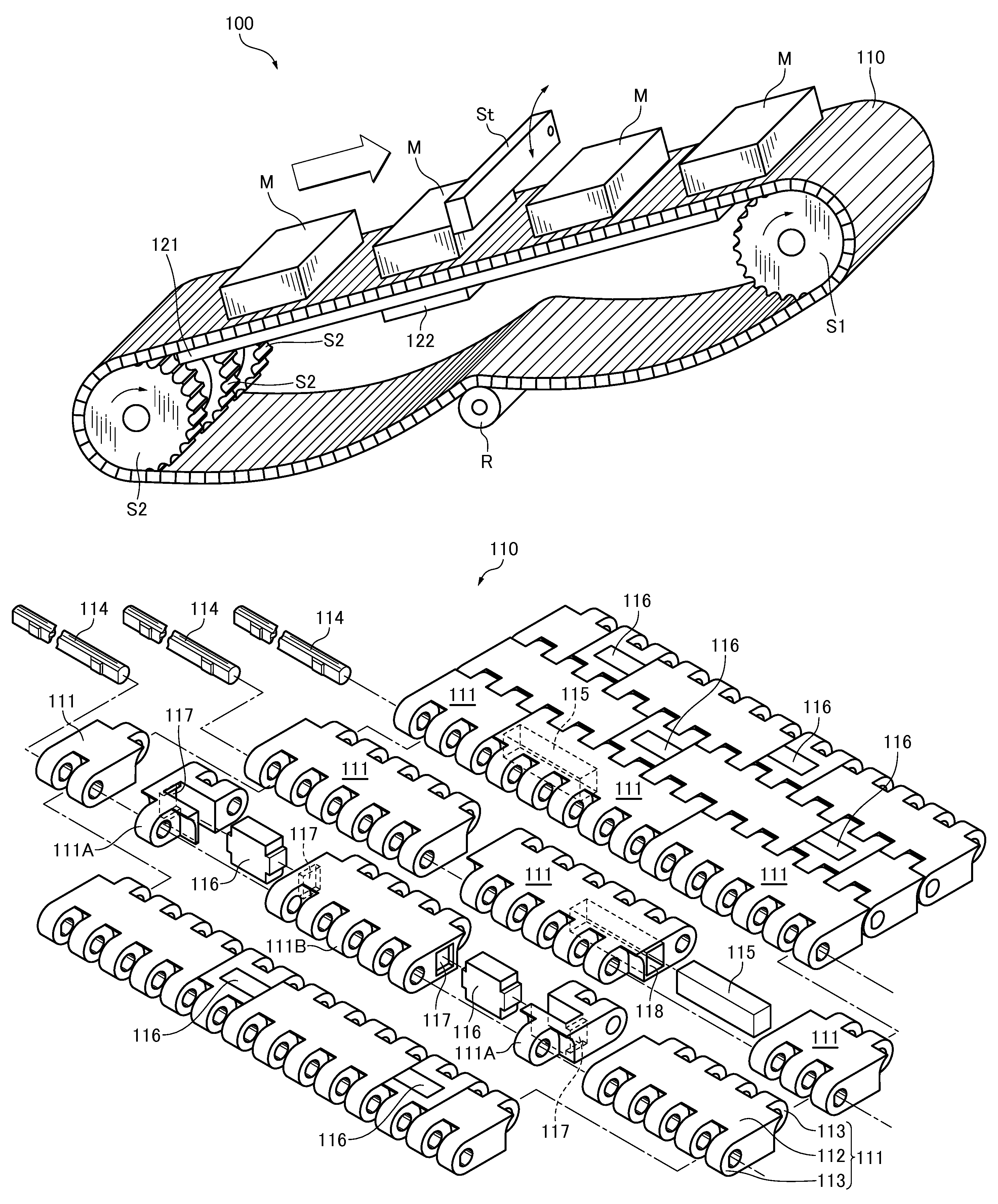
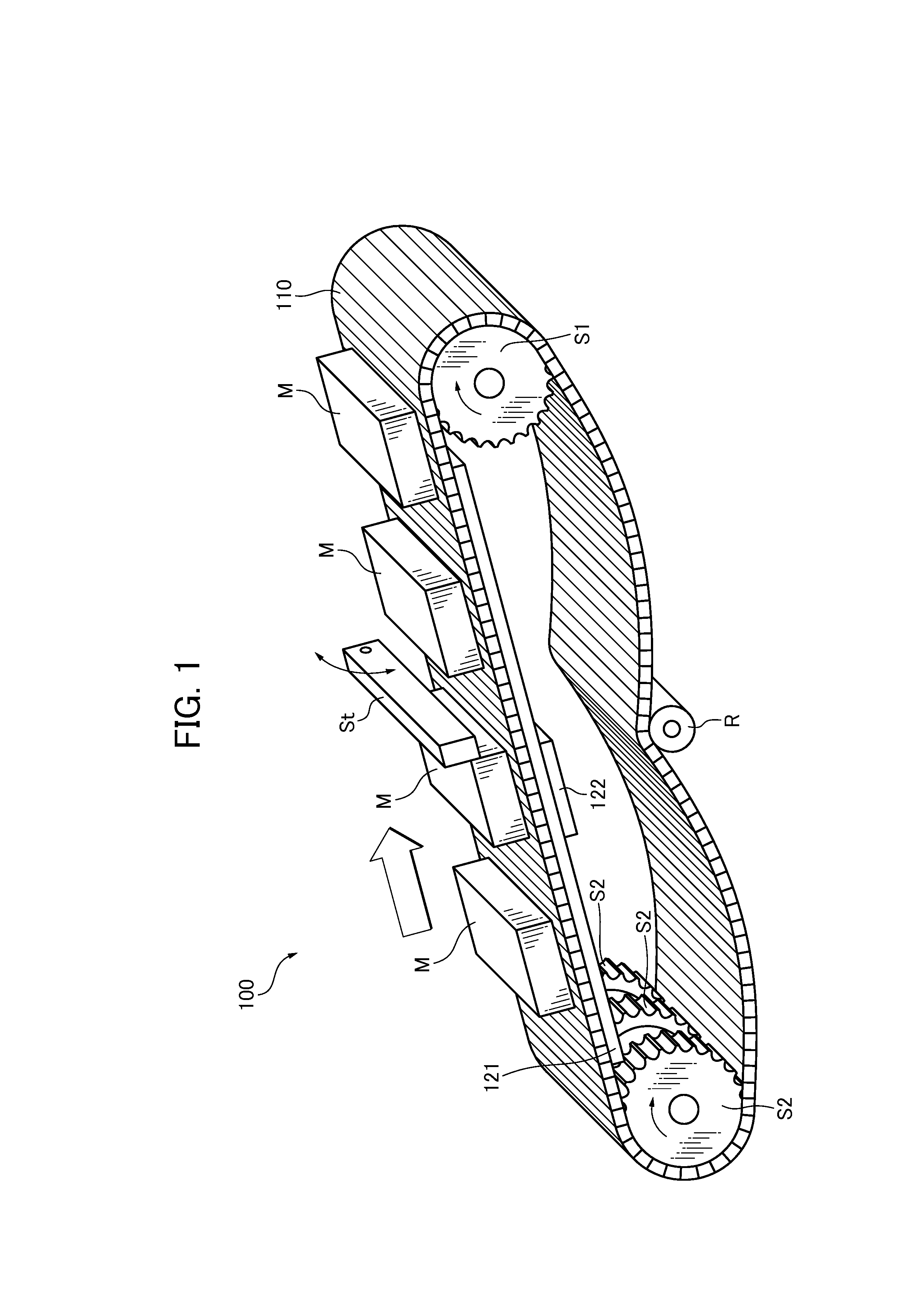
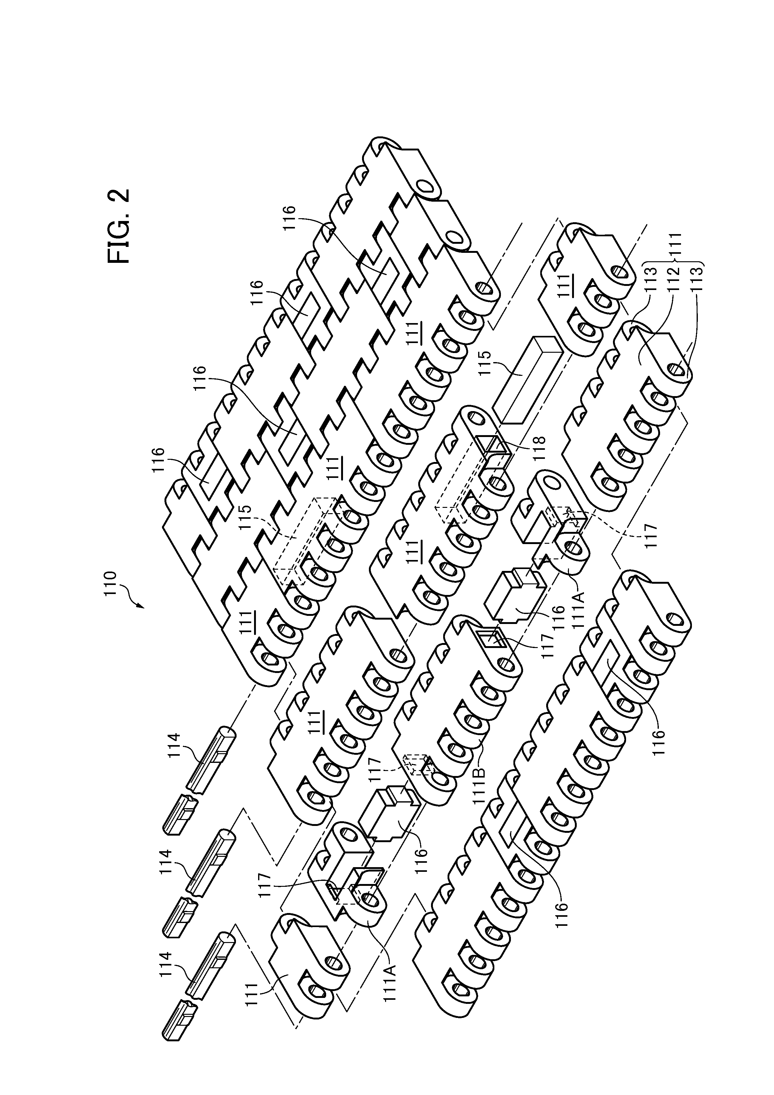
[0043]A chain conveyor apparatus 100 of a first embodiment of the invention will be described below with reference to the drawings.

[0044]FIG. 1 is a general view showing a mode of use of the chain conveyor apparatus 100 of a first embodiment of the invention. FIG. 2 is a perspective assembly and exploded view of a conveyor chain 110 of the first embodiment of the invention. FIG. 3 is a plan view of the chain conveyor apparatus 100 of the first embodiment. FIG. 4 is a section of the chain conveyor apparatus 100 taken along a line 4-4 indicated in FIG. 3. FIG. 5 is a section view of the chain conveyor apparatus 100 taken along a line 5-5 indicated in FIG. 3. FIG. 6 is a section view illustrating a condition in which a movable push-up rail 122 shown in FIG. 5 is pushed up in a vertical direction. FIG. 7 is a perspective view showing a synthetic resin link module 111 accommodating an attraction detaching piece 116 shown in FIG. 2. FIG. 8 is a perspective view of the sy...

second embodiment

(Second Embodiment)

[0064]A chain conveyor apparatus 210 of a second embodiment of the invention will be described with reference to the drawings. FIG. 9 is a perspective assembly and exploded view of a conveyor chain 210 of the second embodiment of the invention. FIG. 10 is a plan view of a chain conveyor apparatus of the second embodiment. FIG. 11 is a perspective view of a synthetic resin link module 211 accommodating an attraction detaching piece 216 shown in FIG. 9. FIG. 12 is a perspective view of the synthetic resin link module 211 viewed from an arrow 12 in FIG. 11.

[0065]As compared to the configurations of the chain conveyor apparatus 100 of the first embodiment described above, configurations and parts of the chain conveyor apparatus 210 of the second embodiment are basically the same. The configuration of a synthetic resin link module 211 accommodating an attraction detaching piece 216 is described herein such that the same or corresponding members of the chain conveyor ap...


PUM


Abstract

There is provided a chain conveyor apparatus that realizes an accumulation operating environment that allows metallic articles to be readily and temporarily dammed up and retained at an accumulation position. Reduced power is required to operate the conveyor chain. Articles are attracted to and retained on the conveyor by using the magnetic force of magnet pieces. Attraction detaching pieces are built in rows of synthetic resin link modules to detach and release the articles. A projection driving mechanism is provided along a straight area on an inner circumferential side of the conveyor chain to project the attraction detaching pieces in and out of a loading surface of the rows of synthetic resin link modules.

Description

CROSS REFERENCE TO RELATED APPLICATIONS[0001]The disclosure of Japanese Patent Application No. 2012-127247, filed on Jun. 6, 2012, and on which this application claims priority, is incorporated by reference.FIELD OF THE INVENTION[0002]This invention relates to a chain conveyor apparatus for loading and conveying articles to be conveyed (referred to simply as “articles” hereinafter). More specifically, the invention relates to a chain conveyor apparatus for loading articles such as metallic mechanical parts and bakery trays by securely attracting and retaining the articles by magnetism even in a condition in which a loading surface is inclined or is slippery.BACKGROUND OF THE INVENTION[0003]A known chain conveyor apparatus uses a conveyor chain composed of a large number of conveying link modules. Each link module has a loading surface for loading articles. Each link module has hinge knuckles projecting from front and rear ends of the loading surface. Link pins connect the link modul...

Claims


Application Information

Patent Timeline
Patent Type & Authority Patents(United States)
IPC IPC(8): B65G17/08B65G54/02B65G47/26B65G47/88B65G21/20
CPCB65G17/46B65G47/34B65G47/268B65G47/266B65G2207/30B65G21/2018B65G47/8807B65G47/8823B65G54/02B65G15/32B65G47/8815B65G17/08
Inventor OTA, KEIKO
Owner TSUBAKIMOTO CHAIN CO
Features
  • R&D
  • Intellectual Property
  • Life Sciences
  • Materials
  • Tech Scout
  • Unparalleled Data Quality
  • Higher Quality Content
  • 60% Fewer Hallucinations
Learn More