Work vehicle and control method for work vehicle

a technology for applied in the field of work vehicles and control methods for work vehicles, can solve the problems of operating the operating member of parking brakes, shock may occur due to the rapid acceleration of vehicles, etc., and achieve the effects of suppressing the occurrence, reducing the speed of vehicles, and high driving torqu

US8701818B2Active Publication Date: 2014-04-22KOMATSU LTD
25 Cites 5 Cited by

Patent Information

Authority / Receiving Office
US · United States
Patent Type
Patents(United States)
Current Assignee / Owner
Publication Date
2014-04-22

Smart Images

  • Figure 1
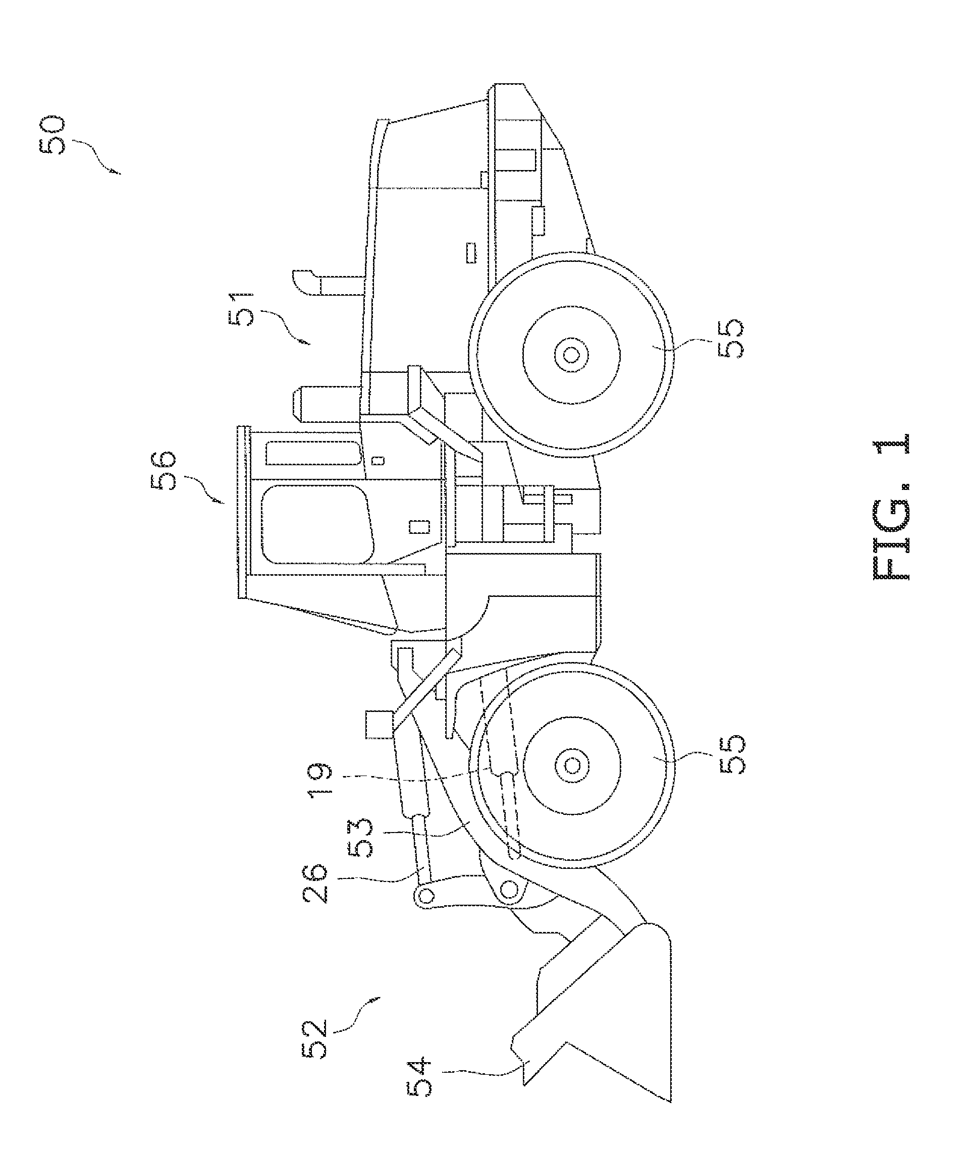
    Figure 1
  • Figure 2
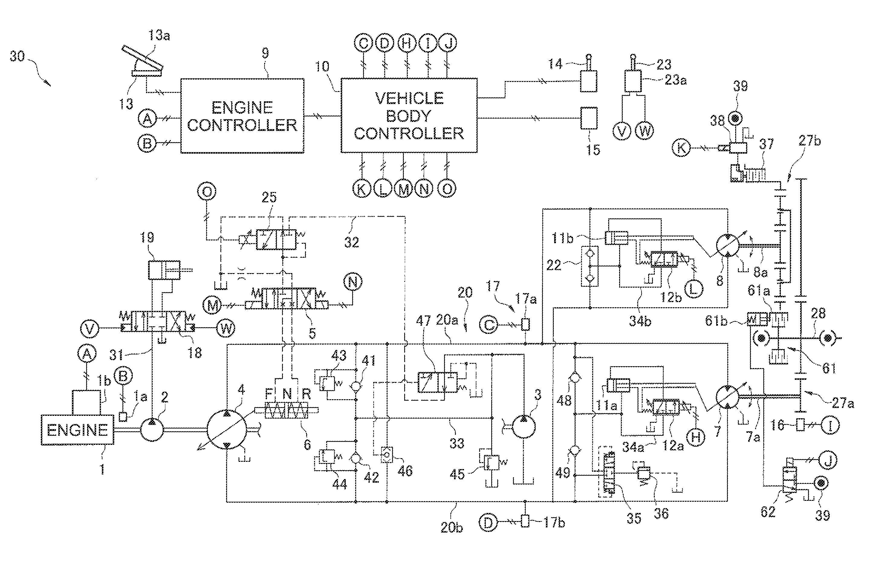
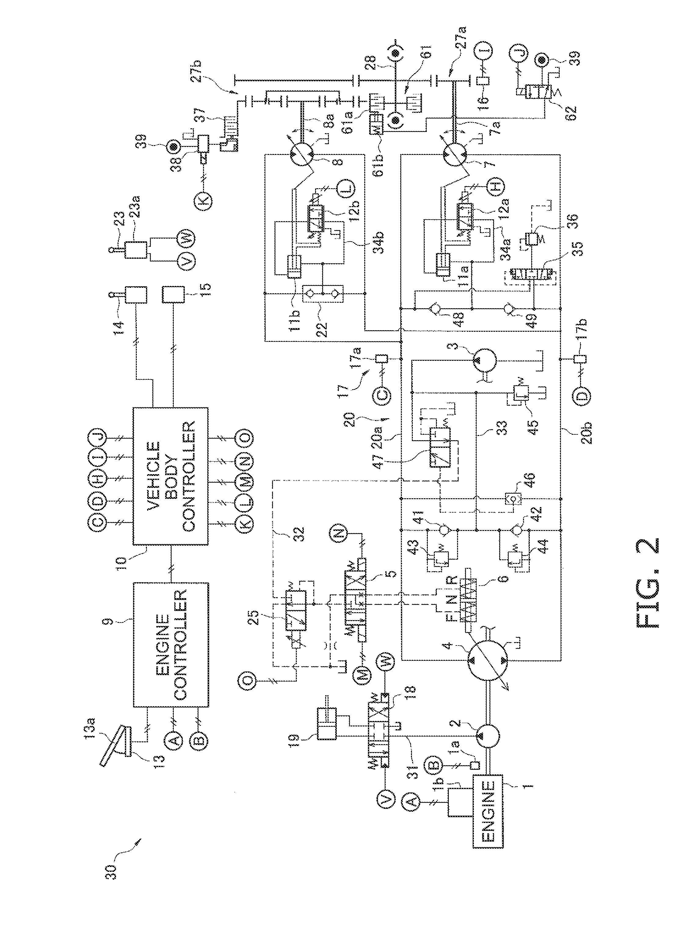
    Figure 2
  • Figure 3
    Figure 3
Patent Text Reader

Abstract

A working vehicle includes an engine, a hydraulic pump, a first hydraulic motor, a vehicle speed detecting unit, a parking brake, a parking brake operating member and a control unit. The control unit is configured to determine whether the vehicle speed is equal to or greater than a predetermined threshold when the parking brake operating member is operated. The control unit is configured to execute a brake control that decreases a displacement of the first hydraulic pump and increases a displacement of the first hydraulic motor without activating the parking brake when the vehicle speed is equal to or greater than the predetermined threshold in a state when the vehicle is traveling, and to activate the parking brake when the vehicle speed falls below the predetermined threshold.
Need to check novelty before this filing date? Find Prior Art

Description

CROSS-REFERENCE TO RELATED APPLICATIONS

[0001] This application claims priority to Japanese Patent Application No. 2012-075600 filed on Mar. 29, 2012, the disclosure of which is hereby incorporated herein by reference in its entirety.TECHNICAL FIELD

[0002] The present invention relates to a work vehicle and a control method for a work vehicle.BACKGROUND ART

[0003] A so-called hydrostatic transmission (HST) is generally installed in a work vehicle such as a wheel loader and the like. In a HST type of work vehicle, a hydraulic pump is driven by an engine and a hydraulic motor for traveling is driven by hydraulic fluid discharged from the hydraulic pump. As a result, the work vehicle travels. Vehicle speed and tractive force can be controlled in this type of HST work vehicle by controlling the engine rotation speed, the displacement of the hydraulic pump, and the displacement of the hydraulic motor for traveling (see International Publication WO 2002 / 050454).

[0004] The work vehicle also inclu...

Examples

Embodiment Construction

[0024]Herein, a work vehicle 50 according to a first embodiment of the present invention will be explained in reference to the accompanying drawings FIG. 1 is a side view of the work vehicle 50. The work vehicle 50 is a wheel loader. The work vehicle 50 includes a vehicle body 51, working equipment 52, a plurality of tires 55, and a cab 56. The working equipment 52 is mounted onto a front portion of the vehicle body 51. The working equipment 52 includes a boom 53, a bucket 54, a lifting cylinder 119, and a bucket cylinder 26. The boom 53 is a member for lifting the bucket 54. The boom 53 is driven by the lift cylinder 19. The bucket 54 is attached to the tip of the boom 53. The bucket 54 is dumped and tilted due to the bucket cylinder 26. The cab 56 is mounted on the vehicle body 51.

[0025]FIG. 2 is a block diagram showing a configuration of a hydraulic drive mechanism 30 installed in the work vehicle 50. The hydraulic drive mechanism 30 mainly includes an engine 1, a second hydrauli...