Shielding flaw detection and measurement in quadrature amplitude modulated cable telecommunications environment

a technology of shielding flaws and telecommunications environment, which is applied in the direction of transmission monitoring, line-faulst/interference reduction, and baseband system details, etc., can solve the problems of degrading or interfering with the signal being carried by the cable telecommunication system, consuming finite bandwidth, and ingress of signals into the cabl

Active Publication Date: 2014-06-10
COMSONICS
View PDF11 Cites 10 Cited by
  • Summary
  • Abstract
  • Description
  • Claims
  • Application Information

AI Technical Summary

Benefits of technology

[0010]It is another object of the present invention to provide robust detection of shielding flaws in combination with a robust and unambiguous identification of the cable telecommunication system from which the egress signal emanates.

Problems solved by technology

However, flaws in cable shielding in cable telecommunication systems can allow signal egress which can potentially interfere with broadcast communications and potentially cause hazards.
Reciprocally, flaws in cable shielding can permit signal ingress into the cable from the environment and degrade or interfere with the signal being carried by the cable telecommunication system.
Accordingly, a problem with all such systems is to identify a received signal as one originating in the cable telecommunications system and numerous techniques have been developed to effectively verify or authenticate a detected signal.
An additional issue that follows from this problem is that a signal which is unique to the cable telecommunication system and distinguishable from broadband noise (e.g. a marker signal) necessarily consumes a finite amount of bandwidth and / or has the potential for interfering with the signal carried by the cable telecommunication system.
However, at the present time, the need to carry ever greater amounts of information (e.g. for high definition television (HDTV) and the like) has resulted in the choice of complex modulation schemes such as quadrature amplitude modulation (QAM) to multiplex signals which are, themselves, more complex and have increased data content.
Such an allocation of bandwidth thus reduces the otherwise available bandwidth of the cable telecommunication system and is essentially a large fixed cost of operating the system.
Even with the allocation of economically significant bandwidth to the shielding flaw detection function, detection is not robust and, where two or more cable telecommunication systems may be present in the same geographic area, identification of the system having the shielding flaw can often not be performed unless the marker signal is particularly complex; requiring more than minimal bandwidth allocation.

Method used


Image

  • Shielding flaw detection and measurement in quadrature amplitude modulated cable telecommunications environment
  • Shielding flaw detection and measurement in quadrature amplitude modulated cable telecommunications environment
  • Shielding flaw detection and measurement in quadrature amplitude modulated cable telecommunications environment

Examples


Embodiment Construction

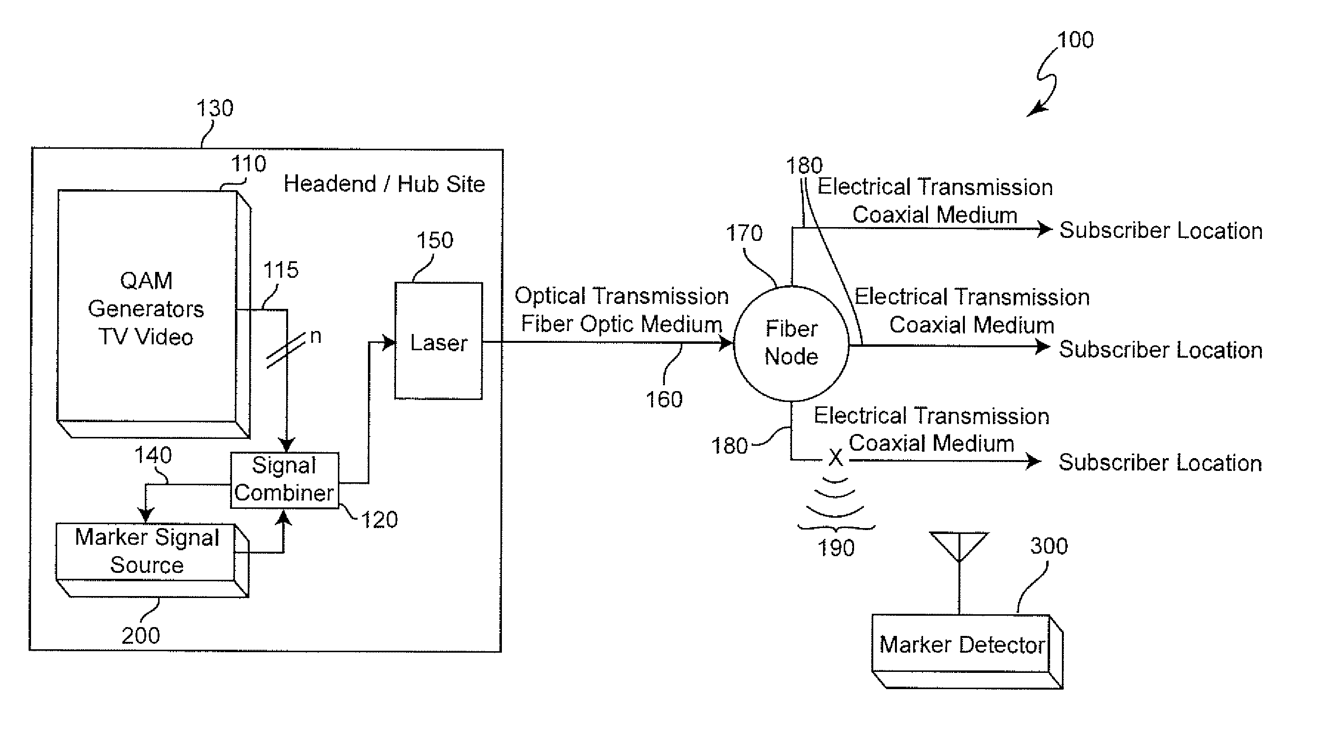
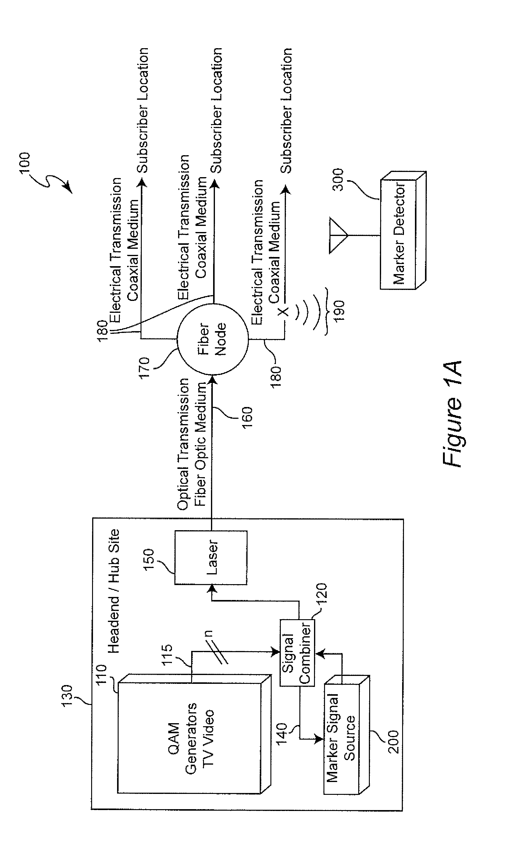
[0019]Referring now to the drawings, and more particularly to FIG. 1A, there is shown a high-level block diagram of the overall cable telecommunication system 100 in accordance with the present invention. It should be appreciated that the block diagram of FIG. 1 can also be understood as a flow chart depicting the methodology of the invention or a data flow diagram. It should also be appreciated that the depiction of the telecommunication system 100 shown in FIG. 1A reflects current technology in the constitution of the telecommunication system as well as integration of the invention into that environment and thus no portion of the drawings is admitted to be prior art in regard to the present invention. However, it should be understood that the invention can be practiced with legacy (e.g. analog) cable telecommunication systems as well as all-digital and other systems which may be developed or foreseen. The application to systems including some or all of the data input from QAM gene...


PUM


Abstract

Signal egress from a shielding flaw in a cable telecommunication system is detected, even where signals carried by the cable telecommunication system are quadrature amplitude modulated signals that statistically resemble broadband noise by generating a marker signal comprising a double side band, suppressed carrier signal in the fringes of contiguous frequency bands and at a power level which cannot cause perceptible interference with signals in those contiguous frequency bands. The separation of the sidebands comprising the marker signal can unambiguously identify the marker signal and can distinguish between different cable telecommunication systems installed in the same geographic area. The marker signal can be additionally coded by varying the frequency and / or amplitude of the modulating signal used to create the marker signal.

Description

FIELD OF THE INVENTION[0001]The present invention generally relates to maintenance of cable telecommunication systems and, more particularly, to detection of cable shielding flaws and measurement of signal egress in such systems in which the communicated signal is quadrature amplitude modulated (QAM).BACKGROUND OF THE INVENTION[0002]Cable telecommunications systems have been known for a number of years and are currently gaining in popularity and coverage for the distribution of television programming, telephone service and networking of computers such as providing Internet access since they can carry many signals over a wide bandwidth with little, if any interference or distortion, particularly as data transmission rates have increased to accommodate high definition television, increased volume of digital communication and the like. By the same token, since these communications are intended to be confined within the cable system, the increased bandwidth required for such communicati...

Claims


Application Information

Patent Timeline
Patent Type & Authority Patents(United States)
IPC IPC(8): H04L1/20G01R31/28
CPCH04L27/367H04L25/08G01R31/021H04L43/50H04L27/3405H04B3/46G01R31/58H04W24/08
Inventor MURPHY, JOHN J.ZIMMERMAN, DENNIS A.
Owner COMSONICS
Why Eureka
Try Eureka