Display apparatus, quantity-of-light adjusting method for display apparatus and electronic equipment

a technology of display apparatus and quantity of light, which is applied in the direction of instruments, static indicating devices, electroluminescent light sources, etc., to achieve the effects of reducing the luminance of light sources, constant chromaticity, and extending the range of luminance control in the display apparatus in the electronic equipmen

Active Publication Date: 2014-09-09
SATURN LICENSING LLC
View PDF30 Cites 0 Cited by
  • Summary
  • Abstract
  • Description
  • Claims
  • Application Information

AI Technical Summary

Benefits of technology

[0022]According to an embodiment of the invention, since a light-on period with pulse width modulation and a light-off period when the light source is turned off are provided so that the quantity of light of the light source can be adjusted with pulse width modulation based on the ratio. Therefore, the luminance of the light source can be sufficiently decreased by defining the pulse width for pulse width modulation so as to keep constant chromaticity.
[0023]In this case, in order to adjust the quantity of light of the light source to a predefined quantity of light or larger, the control means may perform control with the pulse width by defining the ratio of the light-on period at 100% until the pulse width of pulse width modulation corresponding to the quantity of light is obtained, and, in order to adjust the quantity of light of the light source to the quantity of light smaller than the predefined quantity of light, the control means may perform control with the ratio of the light-on period by keeping the pulse width constant. Thus, both of the stability of chromaticity and the adjustment of luminance can be obtained by performing the adjustment only with pulse width modulation in order to obtain a predefined quantity of light or larger and performing control with the ratio of the light-on period to the light-off period with a constant pulse width of pulse width modulation in order to obtain the quantity of light smaller than the predefined quantity of light.
[0026]According to this embodiment of the invention, since a light-on period with pulse width modulation and a light-off period when the light source is turned off are provided so that the quantity of light of the light source can be adjusted with pulse width modulation based on the ratio. Therefore, the luminance of the light source can be sufficiently decreased by defining the pulse width for pulse width modulation so as to keep constant chromaticity.
[0030]According to this embodiment of the invention, in order to adjust the quantity of light of the light source provided on the display device with pulse width modulation, a light-on period with pulse width modulation and a light-off period when the light source is turned off are provided so that the quantity of light of the light source in the display apparatus can be adjusted with pulse width modulation based on the ratio. Therefore, the luminance of the light source can be sufficiently decreased by defining the pulse width for pulse width modulation so as to keep constant chromaticity. Therefore, the range of the luminance control in the display apparatus in the electronic equipment can be extended.
[0031]Therefore, according to the embodiments of the invention, the luminance can be sufficiently decreased with the chromaticity of a light source, which irradiates light to display means, kept constant.

Problems solved by technology

However, it is difficult for the generally-considered three quantity-of-light adjusting method to keep constant chromaticity and decrease the luminance sufficiently.

Method used


Image

  • Display apparatus, quantity-of-light adjusting method for display apparatus and electronic equipment
  • Display apparatus, quantity-of-light adjusting method for display apparatus and electronic equipment
  • Display apparatus, quantity-of-light adjusting method for display apparatus and electronic equipment

Examples


Embodiment Construction

[0053]With reference to drawings, embodiments of the invention will be described.

[Layout in LED Back Light]

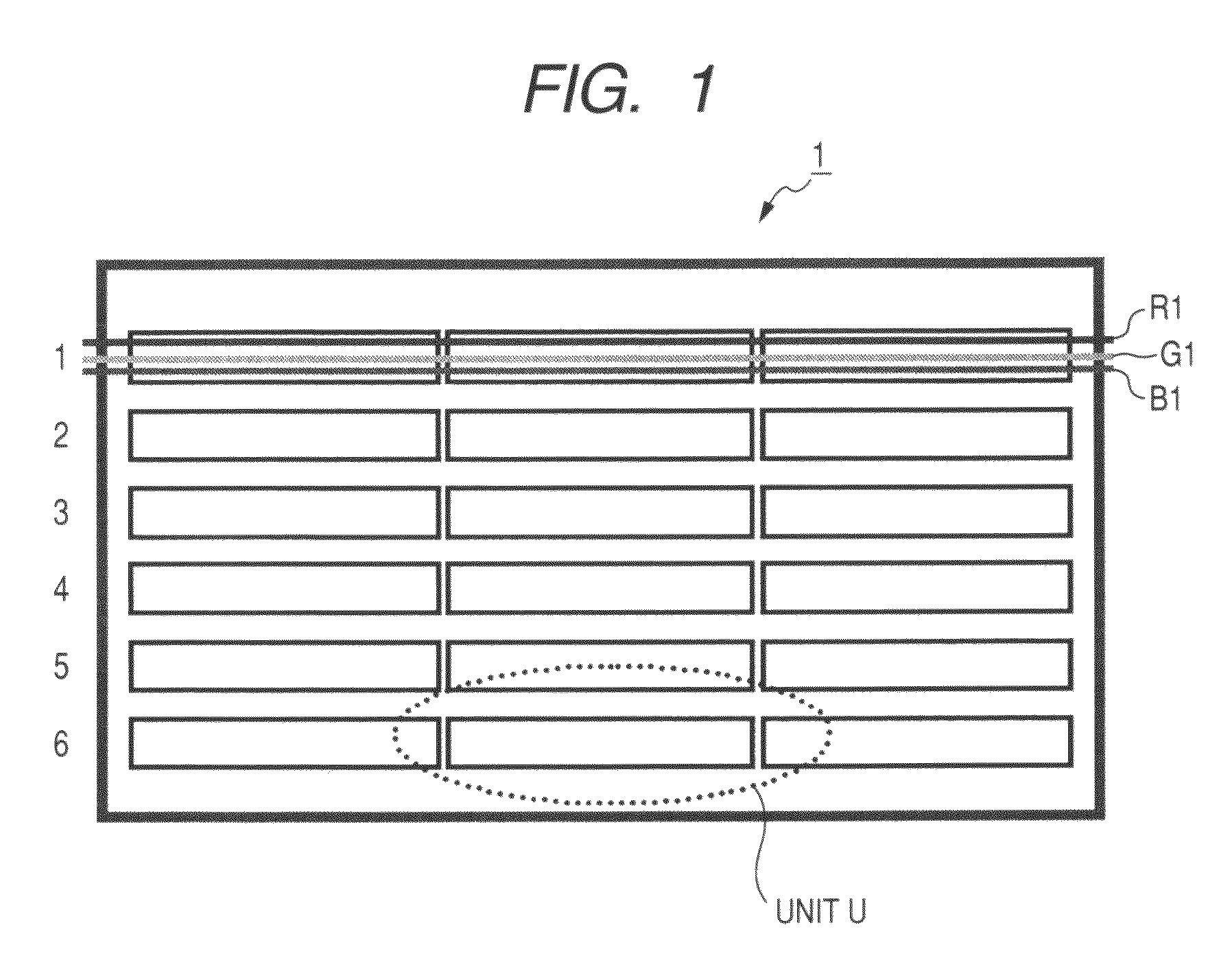
[0054]FIG. 1 is a schematic plan view illustrating the layout in an LED back light. An LED back light is placed at the back of display means (such as a liquid crystal panel) in a display apparatus 1 and supplies light to the display means. In the LED back light, one unit U has multiple R, G and B LEDs, and the units U are placed horizontally and vertically. As the area of the display means such as a liquid crystal panel increases, the number of units U disposed vertically and horizontally increases. However, one unit U may be provided for display means in a smaller area.

[Configuration of Unit]

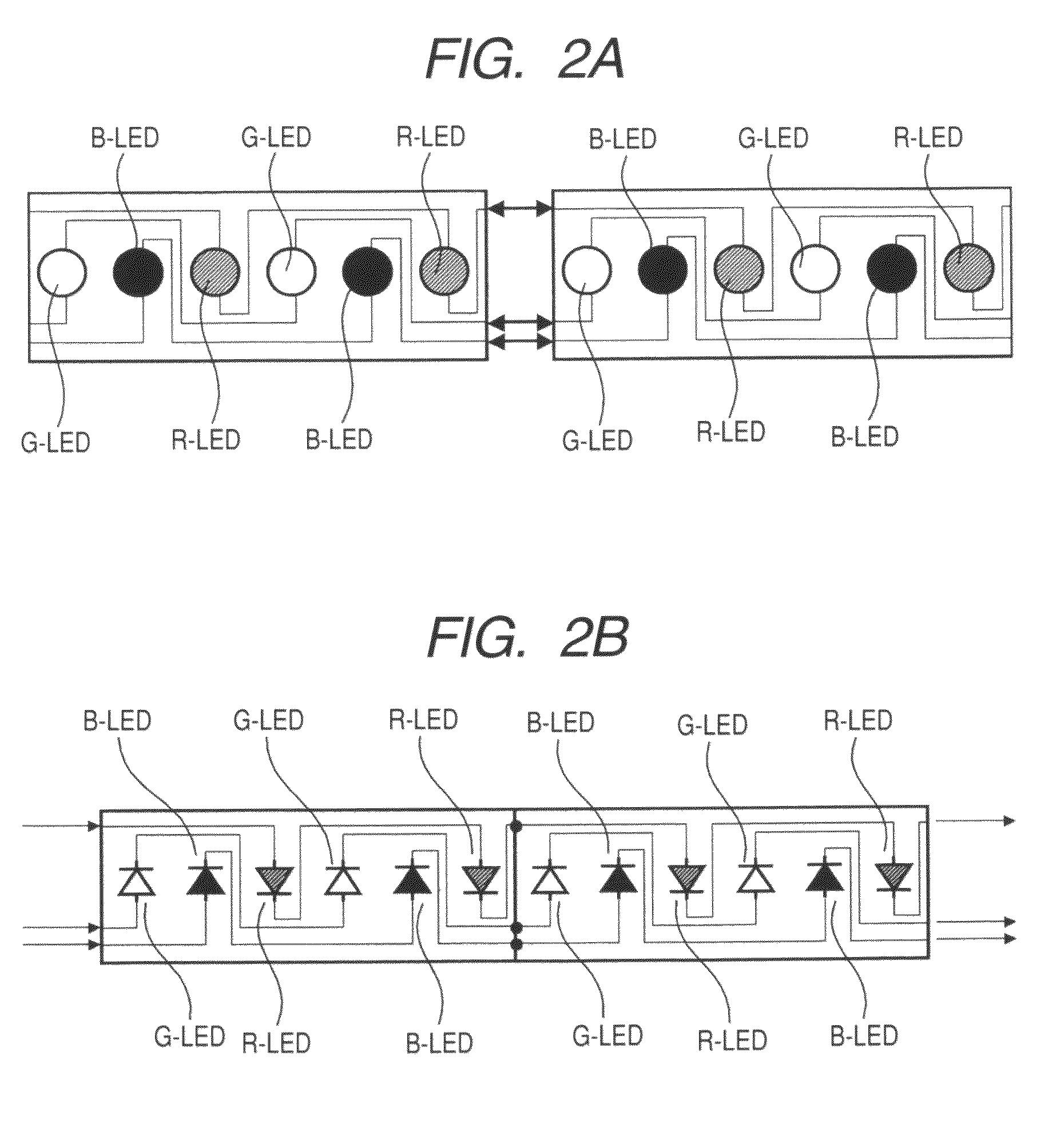
[0055]FIGS. 2A and 2B are schematic diagrams illustrating a configuration of an LED unit employed in an LED back light, and FIG. 2A is a layout diagram, and FIG. 2B is a circuit diagram. In one unit, R (red), G (green) and B (Blue) LEDs (or R-LED, G-LED and B-LED) are laid out in a predete...


PUM

PropertyMeasurementUnit
frequencyaaaaaaaaaa
frequencyaaaaaaaaaa
frequencyaaaaaaaaaa

Abstract

A display apparatus includes display means for displaying an image, a light source that irradiates light to the display means, and control means for controlling the quantity of light of the light source with pulse width modulation. The control means controls the quantity of light of the light source based on the ratio of the light-on period with pulse width modulation to the light-off period when the light source is turned off.

Description

CROSS REFERENCES TO RELATED APPLICATIONS[0001]The present application claims priority from Japanese Patent Application JP No. 2007-268576 filed in the Japanese Patent Office on Oct. 16, 2007, the entire content of which is incorporated herein by reference.BACKGROUND OF THE INVENTION[0002]1. Field of the Invention[0003]The present invention relates to a display apparatus that displays an image by irradiating light from a light source to display means, a quantity-of-light adjusting method for a display apparatus and electronic equipment.[0004]2. Description of the Related Art[0005]Liquid crystal displays including a liquid crystal television may use an LED (or light emitting diode) device as a back light thereof for one advantage that the range of the luminance control is wider than that of a CCFL (Cold Cathode Fluorescent Lamp) (refer to JP-A-2005-310997 (Patent Document 1), for example).[0006]The CCFL may also control the luminance and mainly includes two methods of voltage light co...

Claims


Application Information

Patent Timeline
Patent Type & Authority Patents(United States)
IPC IPC(8): G09G3/34G02F1/133G09G3/20G09G3/36H01L33/00H05B44/00
CPCH05B33/0869G09G2320/041G09G2320/0666G09G2320/064G09G2360/145H05B45/22H05B45/37
Inventor ICHIKAWA, HIROAKIKIKUCHI, KENICHIHATAJIRI, KIMIO
Owner SATURN LICENSING LLC
Why Eureka
Try Eureka