Antenna device

a technology of antenna and antenna, which is applied in the direction of rhombic antenna, differentially interfering antenna combinations, non-resonant long antennas, etc., can solve the problem of difficult use of antennas for tire pressure detection systems, and achieve the effect of accurate reception of radio waves

Inactive Publication Date: 2014-09-16
TOYOTA JIDOSHA KK
View PDF27 Cites 2 Cited by
  • Summary
  • Abstract
  • Description
  • Claims
  • Application Information

AI Technical Summary

Benefits of technology

[0009]The invention provides an antenna device that is able to accurately receive radio waves coming from a specific direction or accurately radiate radio waves toward a specific direction.

Problems solved by technology

In this case, the size of an antenna according to the above technique is about 50 cm, so it is difficult to use the antenna for the tire pressure detecting system.

Method used


Image

  • Antenna device
  • Antenna device
  • Antenna device

Examples


Embodiment Construction

[0034]Hereinafter, a specific embodiment according to the aspect of the invention will be described with reference to the accompanying drawings; however, the aspect of the invention is not limited to the embodiment.

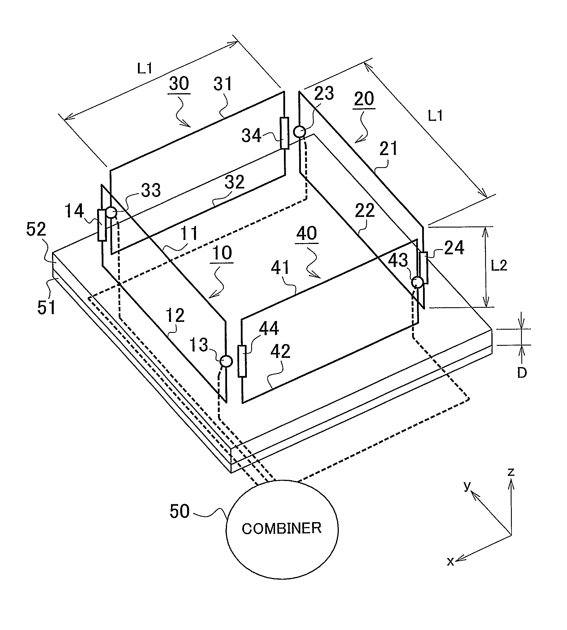
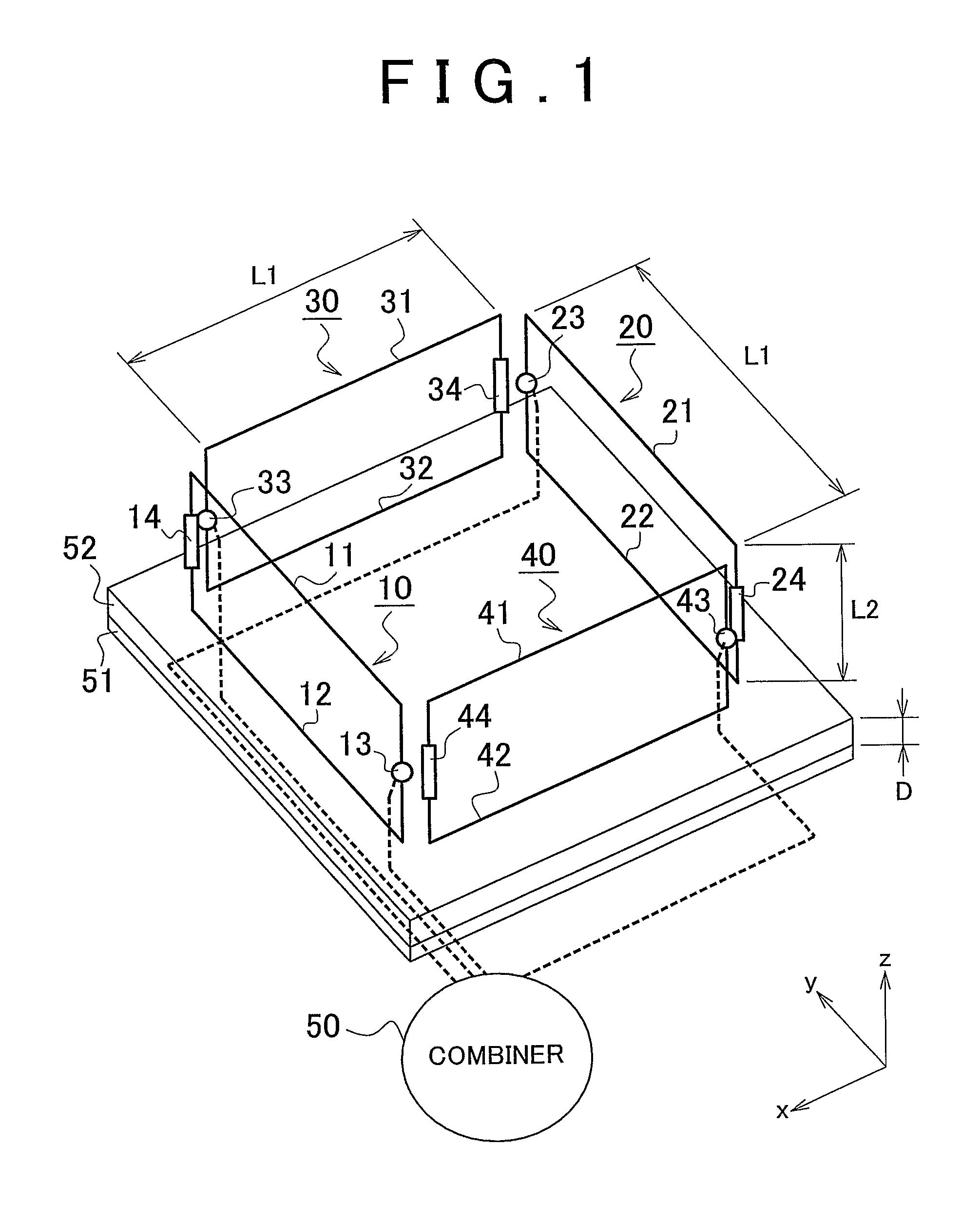
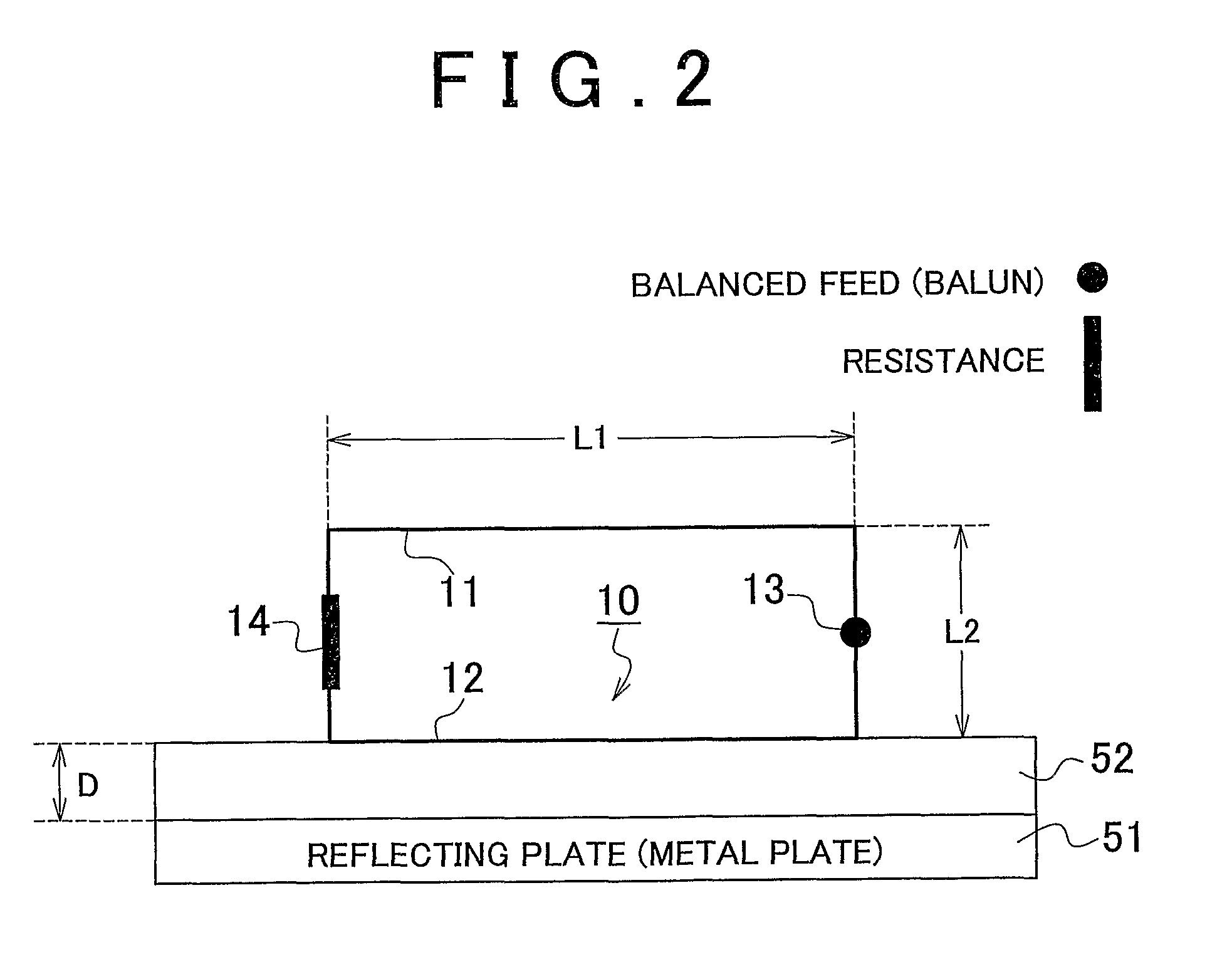
[0035]FIG. 1 is a configuration diagram of a receiving antenna device according to a first embodiment. A wire antenna 10 has a rectangular shape. The wire antenna 10 is formed of a first wire line 11, a second wire line 12, a power receiving point 13 and a terminal resistance 14. The power receiving point 13 is provided at the proximal portions of these wire lines. The terminal resistance 14 is provided at the distal end portion of the antenna and at a connecting point between the first wire line 11 and the second wire line 12. The interval between the first wire line 11 and the second wire line 12 is L2. A wire antenna 20 is provided parallel to the wire antenna 10. The wire antenna 20, as well as the wire antenna 10, has a rectangular shape. The wire antenna 20 is forme...


PUM


Abstract

An antenna device that radiates or receives a radio wave includes: a first wire line; a second wire line that is parallel to the first wire line; a power feeding / receiving point that is provided at proximal portions of the first wire line and second wire line; and a terminal resistance that is provided at distal end portions of the first wire line and second wire line.

Description

BACKGROUND OF THE INVENTION[0001]1. Field of the Invention[0002]The invention relates to an antenna device that radiates or receives radio waves. Specifically, the invention relates to an antenna device that may be applied to a tire pressure detecting device of an automobile.[0003]2. Description of the Related Art[0004]In an existing art, an antenna device described in Japanese Patent Application Publication No. 2001-24431 (JP-A-2001-24431) is known. The antenna device is formed of a feeding antenna disposed upright at the center of a grounded conductor and a plurality of parasitic antennas that are disposed upright around the feeding antenna and that have variably controllable reactances. In this antenna device, the reactances of the surrounding parasitic antennas are electrically varied to thereby control the directivity of the antenna device.[0005]Japanese Patent Application Publication No. 11-88246 (JP-A-11-88246) describes an antenna for a small mobile receiver. In the antenna,...

Claims


Application Information

Patent Timeline
Patent Type & Authority Patents(United States)
IPC IPC(8): H01Q11/06H01Q11/12H01Q11/02H01Q1/22H01Q1/32H01Q3/24H01Q7/00H01Q21/28H01Q21/29
CPCH01Q7/00H01Q21/28H01Q1/2241H01Q1/32H01Q21/29H01Q3/24
Inventor HANAZAWA, MASAHIROIDE, NOBUHIRO
Owner TOYOTA JIDOSHA KK
Why Eureka
Try Eureka