Mixer, matching device, ignition unit, and plasma generator

a technology of ignition unit and mixing device, which is applied in the direction of machines/engines, spark plugs, spark plugs, etc., can solve the problems of transmission capacity of energy on the transmission path of electromagnetic wave, and achieve the reduction of surface creepage, ensuring the transmission efficiency of electromagnetic wave, and suppressing energy leakage.

Inactive Publication Date: 2014-10-14
MAGINEERING INC
View PDF14 Cites 6 Cited by
  • Summary
  • Abstract
  • Description
  • Claims
  • Application Information

AI Technical Summary

Benefits of technology

[0032]According to the present invention, the mixer is of a coaxial structure. Therefore, mixing with the pulse voltage and transmission of the electromagnetic wave may be achieved without performing mode conversion of the electromagnetic wave, which helps to ensure the transmission efficiency of the electromagnetic wave. In addition, occurrence of surface creepage may be reduced, and leakage of energy may be suppressed, so that voltage resistance may be improved, thereby helping to ensure transferred energy and improve electrical robustness. In addition, in the coaxial structure, most members are cylindrical, thereby achieving greater rigidity than the structural weight, which helps to ensure firmness. In addition, by using the coaxial structure, the minimum width of the shape may be decreased, which helps to improve mountability.
[0033]Moreover, the transmission path of the pulse voltage is shielded by the coaxial structure. Therefore, leakage of electromagnetic noise when the pulse voltage is generated may be reduced, thereby making countermeasures for the noise be simple, and improving the mountability. In addition, loss of transferred energy incurred by noise countermeasures such as electric resistance may be suppressed, thereby ensuring transmission efficiency of energy.

Problems solved by technology

On the other hand, the transmission path of the electromagnetic wave from an oscillator of the electromagnetic wave to the electromagnetic wave radiator becomes complex.
When the manner is applied to ignition of an internal-combustion engine, how to ensure mountability regarding the internal-combustion engine and firmness capable of enduring the environment when the internal-combustion engine is in operation is a problem to be solved.
Therefore, how to ensure transmission capacity and transmission efficiency of energy on the transmission path of the electromagnetic wave is a problem to be solved.
The plasma generation device recorded in Patent Document 4 does not give full consideration to such problems.

Method used


Image

  • Mixer, matching device, ignition unit, and plasma generator
  • Mixer, matching device, ignition unit, and plasma generator
  • Mixer, matching device, ignition unit, and plasma generator

Examples


embodiment 1

Variation 3 of Embodiment 1

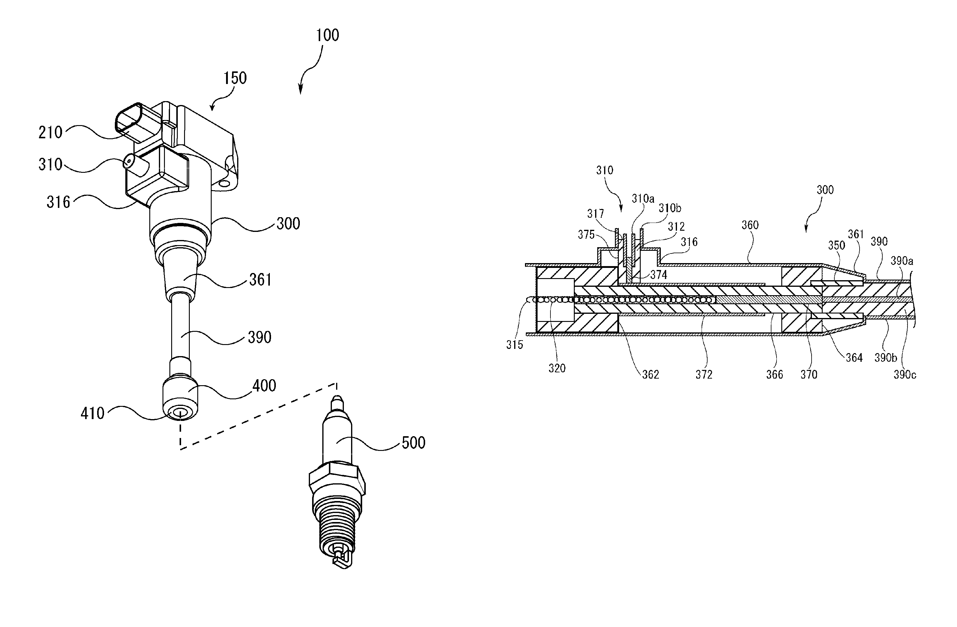
[0110]A variation 3 of the embodiment 1 is illustrated. In the variation 3, as shown in FIG. 8, the electrical conductor rod 370, the dielectric pipe 366 and the outer conductor 390a jointly constitute the extension portion 390. Therefore, the change in impedance at the boundary between the housing 360 and the extension portion 390 is reduced.

Embodiment 2

[0111]An embodiment 2 is illustrated. In the embodiment 2, as shown in FIG. 9, a cylindrical protruding portion 26 is disposed at the base end side of an insulator 22 of a spark plug 20, so as to replace the disposed insulator insertion member 464.

[0112]The cylindrical protruding portion 26 and the insulator 22 of the spark plug 20 are integrally formed. Therefore, for the cylindrical protruding portion 26 at the spark plug 20, discharging between a conductor inside the cylindrical protruding portion 26 and a conductor outside the cylindrical protruding portion 26 is prevented. A dielectric layer 34 of a h...

embodiment 2

Variation 3 of Embodiment 2

[0123]A variation 3 of the embodiment 2 is illustrated. In the variation 3, as shown in FIG. 12, a tapered portion 44 is formed at an end portion, at the mixer 300, of the cylindrical protruding portion 26. The tapered portion 44 has an increasing outer diameter towards the base end of the cylindrical protruding portion 26. Therefore, the change in the impedance of the matching device 400 may be alleviated.

Other Embodiments

[0124]The embodiment may also be implemented in the following manner.

[0125]In the embodiment, the electrical conductor rod 370 may be a cylindrical rod body. In this case, the inner conductor 390a of the extension portion 390 may be inserted into the inside the electrical conductor rod 370. Therefore, the extension portion 390 may be easily connected to one end of the electrical conductor rod 370.

[0126]In addition, in the embodiment, the hybrid output terminal 340 may be configured so that the impedance of the microwave becomes the same ...


PUM


Abstract

A mixer for mixing pulse voltage energy and electromagnetic wave energy in the same transmission line is provided with a first input terminal to which an electromagnetic wave is inputted, a second input terminal to which pulse voltage is inputted, a mixing output terminal from which the pulse voltage and the electromagnetic wave are outputted, a bar-shaped first conductive member of which one end is electrically connected to the second input terminal and the other end is electrically connected to an inner conductor of the mixing output terminal, a cylindrical second conductive member which surrounds the first conductive member with a gap therebetween and is disposed coaxially with the first conductive member and electrically connected to an inner conductor of the first input terminal, and a cylindrical third conductive member which houses the first conductive member and the second conductive member with a gap between the second conductive member and the third conductive member and is disposed coaxially with the first conductive member and the second conductive member and electrically connected to an outer conductor of the first input terminal and an outer conductor of the mixing output terminal.

Description

BACKGROUND OF THE INVENTION[0001]1. Field of the Invention[0002]The present invention relates to a mixer for mixing a pulse voltage and an electromagnetic wave, a matching device for achieving impedance matching of an electromagnetic wave output from the mixer, an ignition unit having the mixer, and a plasma generator having the ignition unit.[0003]2. Related Art[0004]As an alternative method of spark ignition of an internal-combustion engine or a plasma generation method, a technology of generating plasma by using spark discharge and electromagnetic wave radiation together is proposed. Compared with the case in which only an electromagnetic wave is used to generate the plasma, the technology may decrease required energy of the electromagnetic wave for generating the plasma. Patent Document 1 records a plasma generator, in which an antenna is configured near a discharge electrode of a spark plug. In addition, Patent Document 1 and Patent Document 2 record a spark plug configured wit...

Claims


Application Information

Patent Timeline
Patent Type & Authority Patents(United States)
IPC IPC(8): F23Q3/00F02P3/01F02P9/00F02P23/04H05H1/36H05H1/46H05H1/52
CPCH05H1/36H05H1/46F02P9/007F02P3/01H05H1/52F02P23/04H05H2001/4682F02P3/04H05H1/48H05H2242/26H01T13/05
Inventor IKEDA, YUJIMAKITA, MINORUMOON, AHSA
Owner MAGINEERING INC
Why Eureka
Try Eureka