Supercharge Your Innovation With Domain-Expert AI Agents!

Lighting system, electrode device and light source

a technology of electrode devices and light sources, applied in the direction of lighting support devices, discharge tubes, luminescent screens, etc., can solve the problems of sls lighting systems that allow unobtrusive integration of lighting into buildings, limit the full potential of sls, and various problems of known systems, so as to increase the chance of correctly positioning the light sour

Inactive Publication Date: 2014-12-30
KONINK PHILIPS ELECTRONICS NV +1
View PDF17 Cites 1 Cited by
  • Summary
  • Abstract
  • Description
  • Claims
  • Application Information

AI Technical Summary

Benefits of technology

This configuration enhances flexibility, reduces heat management issues, ensures reliable contact, and allows for precise positioning without leaving visible traces, thereby improving user-friendliness and aesthetic integration.

Problems solved by technology

This, however, poses limitations on exploiting the full potential of SLS.
For example, it has already been proved that slim SLS lighting systems allow unobtrusive integration of lighting into a building.
However, various problems are encountered with the known system, in particular:
difficulties in managing heat generated by the at least one light source during operation because of the electrically (and thermally) isolating layer between the electrodes;
due to switching the light source on and off, the electric contacts between the contact elements of the at least one light source and the electrodes will deteriorate and become unreliable as a result of the repeatedly thermal expansion and shrinkage of the contact elements of the at least one light source;
in current embodiments, users are limited to the use of pinboard-like walls if the visibility of the punched holes should diminish after removal of the at least one light source;
the known system is relatively inflexible and incapable of following relatively sharp contours of carrier materials (such as curved walls).

Method used


Image

  • Lighting system, electrode device and light source
  • Lighting system, electrode device and light source
  • Lighting system, electrode device and light source

Examples


first embodiment

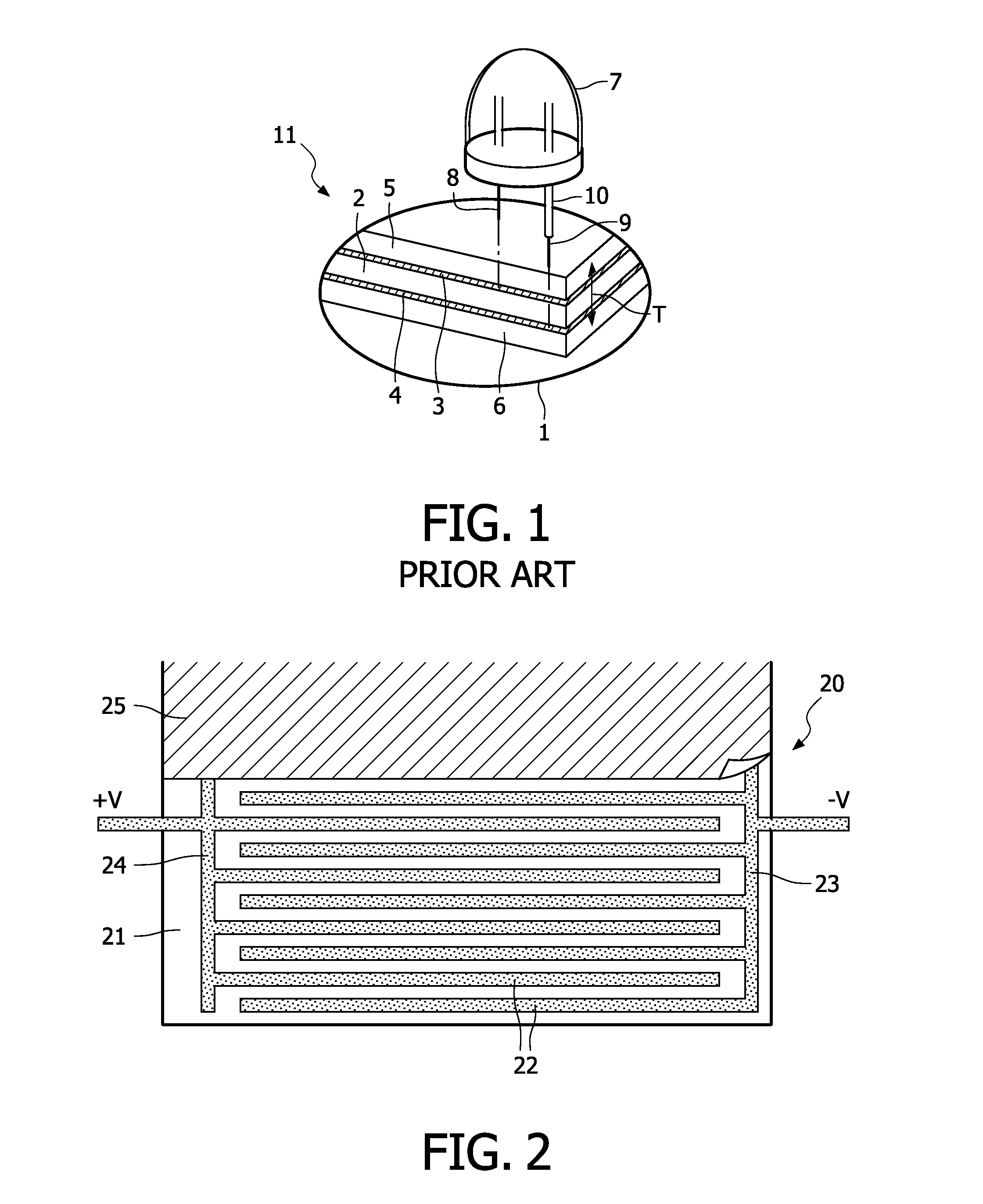
[0029]FIG. 2 is a top view of the electrode device 20 according to the invention. The electrode device comprises a flexible board 21, for example, a printed circuit board, on or in which ferromagnetic strips 22 have been provided. All strips extend in one direction, are placed equidistantly, and are provided essentially in one layer, yielding an electrode device with a thickness of about 2 mm. The strips are electrically connected in such a way that they constitute an interdigitated configuration, i.e. two comb structures having a different electric and permanent magnetic polarity. The first comb 23 is connected to the minus electrode of a power supply and the second comb 24 is connected to the plus electrode of the power supply. The voltage is preferably below 50V, for example, 24V, and DC, but this may be alternatively AC. To avoid visibility of this electric structure to a consumer, the electrode device is optionally covered with a thin foil 25 which is not electrically conductiv...

second embodiment

[0030]FIG. 3 shows the electrode device according to the invention, in which the electrode functionality and ferromagnetic or electromagnetic functionality of the interdigitated electrode configuration of FIG. 2 are separated. The electrode device 30 of the embodiment shown in FIG. 3 comprises a substrate 31 on which a ferromagnetic or electromagnetic layer 32 is provided. This layer may be embodied as one, closed layer or as a patterned structure, for example, a stripe or a block pattern. A printed circuit board 33 (=PCB) with an interdigitated electrode configuration 34, 35 is provided on top of the substrate and its magnetic layer. A protective and / or aesthetic screen 36 is provided on top of the substrate, the magnetic layer and the PCB. A light source (not shown) can be connected to the electrode device via a lamp base (see FIGS. 4A and 4B). In FIG. 3, an equilateral pentangle, i.e. a light source having five electric contacts, schematically represents a mounted light source. E...


PUM


Abstract

A system comprises a light source and an electrode device (20, 30, 60). The light source comprises a base (40) with a base surface (42) on which at least two contact elements are provided. The electrode device has at least two electrodes (23, 24, 34, 35), preferably of ferromagnetic or electromagnetic material and having a different polarity during operation. Adjacent electrodes are arranged at a predetermined electrode distance. Both electrodes are provided in one layer and are arranged in an interdigitated configuration. The light source has at least two, but preferably four contact elements (43, 53, 63) arranged at a mutual spacing which is essentially compatible with said electrode distance.

Description

FIELD OF THE INVENTION[0001]The invention relates to a system as defined in the pre-characterizing part of claim 1. The invention further relates to a light source and an electrode device, both being adapted for use in the system according to the invention.BACKGROUND OF THE INVENTION[0002]Such a system is marketed under the trade name of Dipline and described at the websites http: / / www.magiclite.com / dipline / diplilne.shtml and http: / / www.magiclite.com / downloads / PDFs / dipline.pdf. Dipline lit panel systems operate at low voltages, for example, 12 V or 24V. These systems are promoted as self-powered, flat, flexible panels which serve as an electrified wall or ceiling surface. It allows simple placement of light sources anywhere on a flat surface and has them light up instantly.[0003]In the past few years, many relatively small light sources (=SLS), for example, LED products or miniature halogen lamps, have entered the market. Most of these products are retrofit so that they can be integ...

Claims


Application Information

Patent Timeline
Patent Type & Authority Patents(United States)
IPC IPC(8): F21V21/35H01J13/46H01R4/24F21V21/096F21V23/06F21S2/00F21V21/002F21Y101/00
CPCF21S2/00F21V21/002H01R4/2404F21V23/06F21V21/35F21V21/096H01R4/2406
Inventor WILLEMSEN, OSCAR HENDRIKUSVERBRUGH, STEFAN MARCUSVERHOEVEN, MARKDE HAAS, CORNELIS GERARDUS MARIAVAN BAARDWIJK, MENNODE ZWART, SIEBE TJERKLENDERINK, EGBERT
Owner KONINK PHILIPS ELECTRONICS NV
Features
  • R&D
  • Intellectual Property
  • Life Sciences
  • Materials
  • Tech Scout
  • Unparalleled Data Quality
  • Higher Quality Content
  • 60% Fewer Hallucinations
Learn More