Power converting transformer, vehicle headlight provided with the power converting transformer and motor vehicle provided with the headlight

a technology of transformers and transformer heads, which is applied in the direction of transformer/inductances, magnetic cores, inductances, etc., can solve problems such as transformer failure, transformer failure, transformer failure, etc., to reduce transformer electric characteristics change, reduce transformer failure, and enhance transformer power conversion efficiency and reliability.

Active Publication Date: 2015-05-05
PANASONIC INTELLECTUAL PROPERTY MANAGEMENT CO LTD
View PDF15 Cites 1 Cited by
  • Summary
  • Abstract
  • Description
  • Claims
  • Application Information

AI Technical Summary

Benefits of technology

[0005]In view of the above, the present invention provides a power converting transformer having an I-core and an E-core, which is capable of suppressing occurrence of problems caused by misalignment between the I-core and the E-core.
[0011]The E-core may include an anti-short-circuit groove provided in the base portion near a circumferential edge of the central leg portion to prevent the E-core from being short-circuited with a coil pattern of a wiring board interposed between the I-core and the E-core.
[0015]With the present invention, the I-core is larger in size than the E-core. For this reason, even if the E-core is slightly misaligned with respect to the I-core, the E-core seldom protrudes beyond the I-core. As a result, it becomes possible to suppress occurrence of problems caused by misalignment. Accordingly, it is possible to reduce a change in the electric characteristics of the transformer and a power loss in the circuit, thereby enhancing the power converting efficiency and reliability of the transformer.

Problems solved by technology

As a result, the amount of leaked magnetic fluxes is increased in the transformer, which may possibly lead to a transformation loss.
In an extraordinarily high temperature region, there is a likelihood that a circuit may be destroyed due to an increase in transformation loss and an increase in electric current caused by magnetic saturation.

Method used


Image

  • Power converting transformer, vehicle headlight provided with the power converting transformer and motor vehicle provided with the headlight
  • Power converting transformer, vehicle headlight provided with the power converting transformer and motor vehicle provided with the headlight
  • Power converting transformer, vehicle headlight provided with the power converting transformer and motor vehicle provided with the headlight

Examples


first embodiment

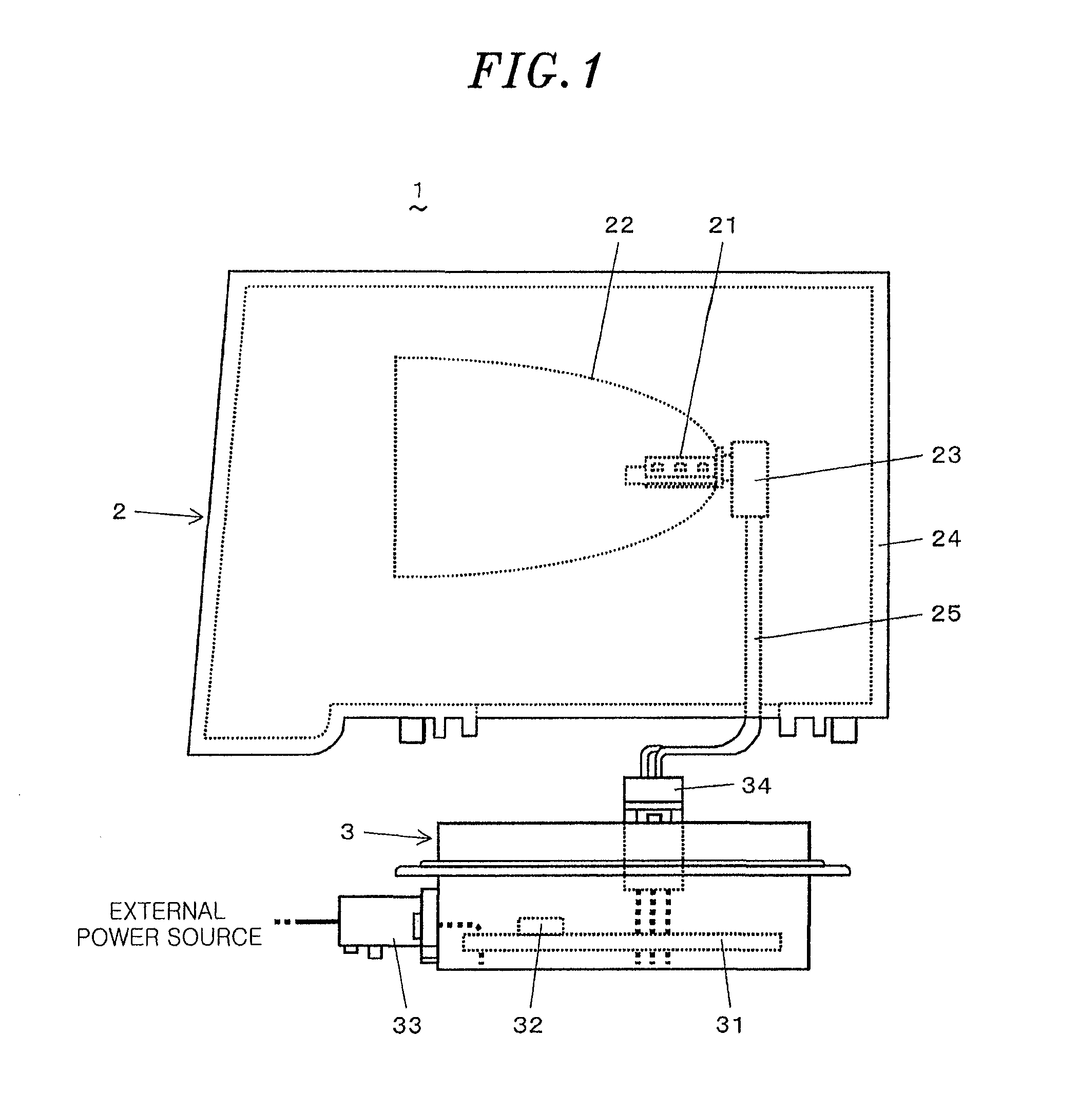
[0036]A motor vehicle according to the present invention, a vehicle headlight mounted to a motor vehicle and a power converting transformer making up the vehicle headlight will now be described with reference to FIGS. 1 through 11F. As shown in FIG. 1, a vehicle headlight 1 includes a lamp device 2 and a lighting device 3 for controlling the lighting of the lamp device 2.

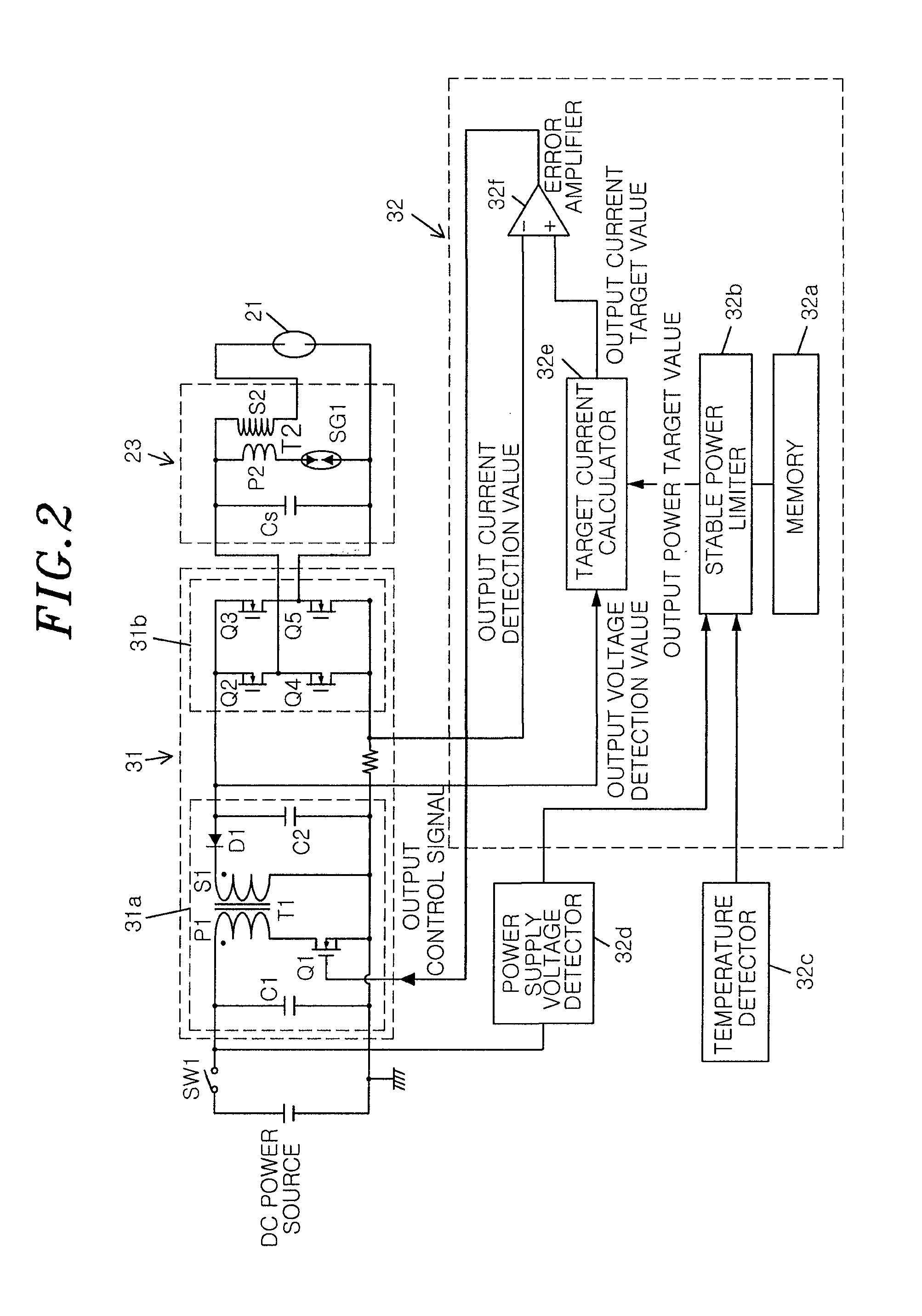
[0037]The lamp device 2 includes a high intensity discharge lamp 21 serving as a light source, a reflector plate 22 for reflecting the light emitted from the discharge lamp 21 to form a specified light distribution pattern, an igniter 23 for causing the discharge lamp 21 to start a discharge operation, and a casing 24 for accommodating the discharge lamp 21, the reflector plate 22 and the igniter 23. The discharge lamp 21 is connected to the lighting device 3 via the igniter 23 by means of a power cable 25.

[0038]The reflector plate 22 is arranged to surround the discharge lamp 21 to reflect the light emitted from th...

second embodiment

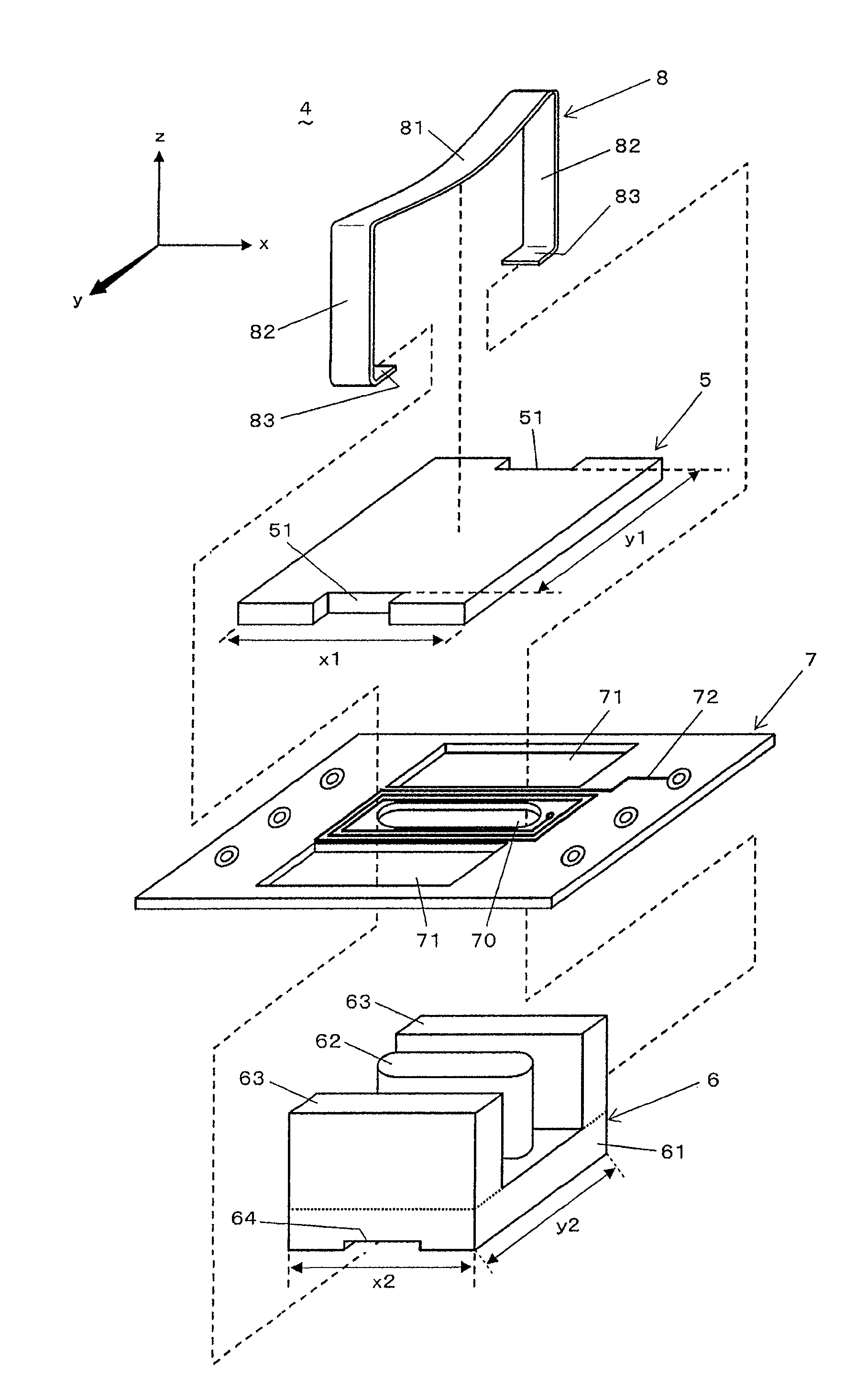
[0062]Next, a transformer according to the present invention will be described with reference to FIGS. 12A to 13D. In the present embodiment, as shown in FIGS. 12A through 12F, the distance y1 between the fixing grooves 51 of the I-core 5 is equal to the y-direction length y2 of the E-core 6. On the other hand, the x-direction length X1 of the I-core 5 is larger than the x-direction length x2 of the E-core 6.

[0063]In case where the I-core 5 and the E-core 6 are pressed and fixed to each other by the fixing spring 8 as shown in FIGS. 13A through 13D, the bottom surfaces of the fixing grooves 51 of the I-core 5 are respectively flush with the opposite side surfaces of the E-core 6 in the y-direction. This is because y1 is set equal to y2. In this regard, the fixing spring 8 is configured such that the arm portions 82 thereof make close contact with the fixing grooves 51 of the I-core 5 and the opposite side surfaces of the E-core 6 in the y-direction (see FIG. 13D).

[0064]Similar to th...


PUM

PropertyMeasurementUnit
voltageaaaaaaaaaa
drive frequencyaaaaaaaaaa
temperatureaaaaaaaaaa

Abstract

In a power converting transformer, an I-core has a pair of fixing grooves provided at centers on opposite side surfaces of the I-core in a y-direction in an xyz orthogonal coordinate system, the fixing grooves extending through the I-core in the z-direction, and an E-core has a pair of fixing recess portions provided at x-direction centers of the y-direction opposite end portions of the base portion on a surface opposite from a surface of the base portion facing the I-core. The I-core and the E-core are pressed and fixed to each other by a fixing spring wrapped around the I-core and the E-core through the fixing grooves and the fixing recess portions. An x-direction length of the E-core is shorter than an x-direction length of the I-core, and a y-direction length of the E-core is shorter than or equal to a y-direction distance between the fixing grooves of the I-core.

Description

FIELD OF THE INVENTION[0001]The present invention relates to a power converting transformer having an I-core and an E-core, a vehicle headlight provided with the power converting transformer and a motor vehicle provided with the vehicle headlight.BACKGROUND OF THE INVENTION[0002]Along with the size reduction of electronic devices, electronic parts mounted on a printed wiring board are becoming smaller in size and thickness. For instance, there is a tendency that a power converting transformer formed by winding a coil around a bobbin is converted to a thin sheet-like transformer.[0003]The sheet-like transformer includes, e.g., a coil pattern formed on a printed wiring board, a pair of transformer cores arranged to grip the coil pattern therebetween and a clip or a fixing spring for joining the transformer cores together (see, e.g., Japanese Patent Application Publication No. 2005-175064). The transformer cores include, e.g., an I-core and an E-core. An inductance value is controlled ...

Claims


Application Information

Patent Timeline
Patent Type & Authority Patents(United States)
IPC IPC(8): H01F5/00H01F27/24H01F17/04H01F27/02H01F27/00H01F27/26H01F27/28
CPCH01F27/008H01F27/263H01F2027/2819B60Q1/04H01F27/24
Inventor NISHIKAWA, MASAHIRONAKANO, TOMOYUKI
Owner PANASONIC INTELLECTUAL PROPERTY MANAGEMENT CO LTD
Why Eureka
Try Eureka