
Portable electric candle having a lamp pendulating and rotating simulataneously

a portable, electric candle technology, applied in the field of electric candles, can solve the problems of inability to continuously give light, lamp failure to accurately simulate an active flame, and user may not be aware of the swinging motion of the flame-simulating lamp

Inactive Publication Date: 2015-09-15
LEE CHONG CEUL
View PDF11 Cites 20 Cited by
  • Summary
  • Abstract
  • Description
  • Claims
  • Application Information

AI Technical Summary

Benefits of technology

[0007]Accordingly, the present invention has been made keeping in mind the above problems occurring in the prior art, and an object of the present invention is to provide a portable electric candle having a lamp able to pendulate and rotate simultaneously, in which the lamp is configured to perform a pendulating motion and a 360 degree angle rotating motion simultaneously, so the lamp can swing irrespective of viewing directions of a user and can better approximate a natural flame.

Problems solved by technology

A candle made of a flammable solid material, such as paraffin, cannot continuously give light for a lengthy period time, requires careful handling and may cause a fire.
However, the above-mentioned technology is problematic in that the lamp of the lamp unit is configured to repeat a pendulating motion, so the lamp fails to accurately simulate an active flame.
Further, when a user views the pendulating lamp in the same direction as a swinging direction of the pendulum, the user may not be aware of the swinging motion of the flame-simulating lamp.

Method used


Image

  • Portable electric candle having a lamp pendulating and rotating simulataneously
  • Portable electric candle having a lamp pendulating and rotating simulataneously
  • Portable electric candle having a lamp pendulating and rotating simulataneously

Examples


Embodiment Construction

[0030]Hereinbelow, preferred embodiments of the present invention will be described in detail with reference to the accompanying drawings. The embodiments are provided for only the purpose of clear understanding of the present invention, so it should be understood that the present invention is not limited to the embodiments.

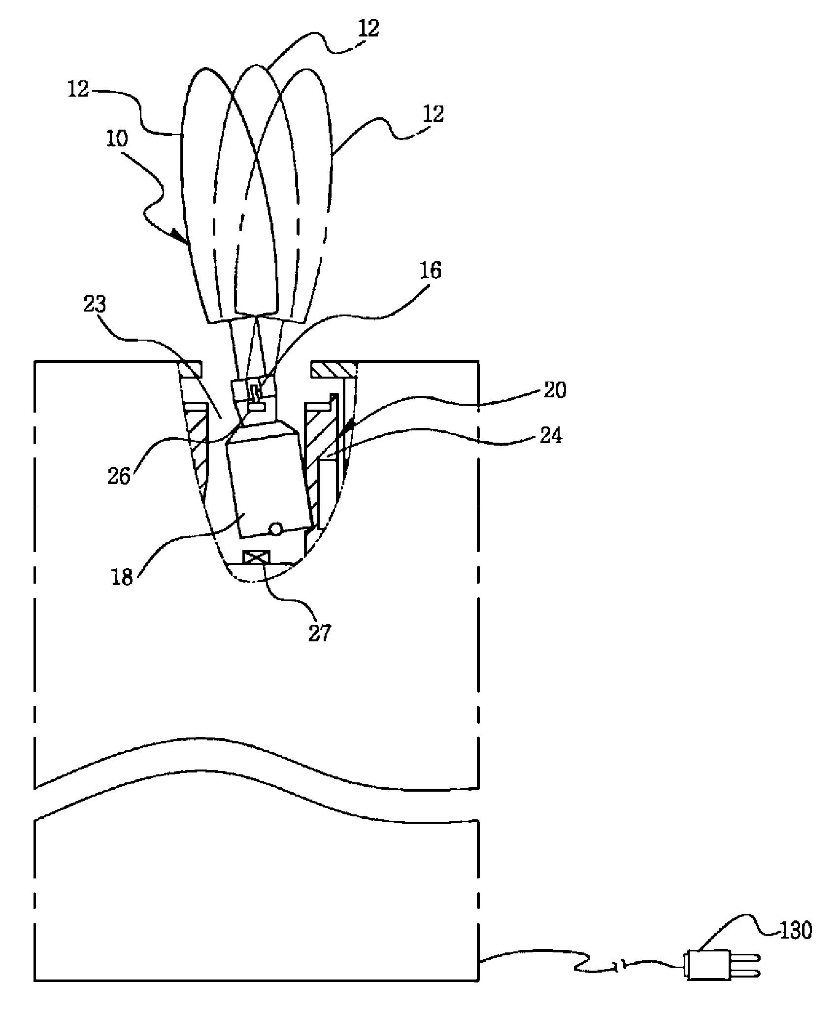
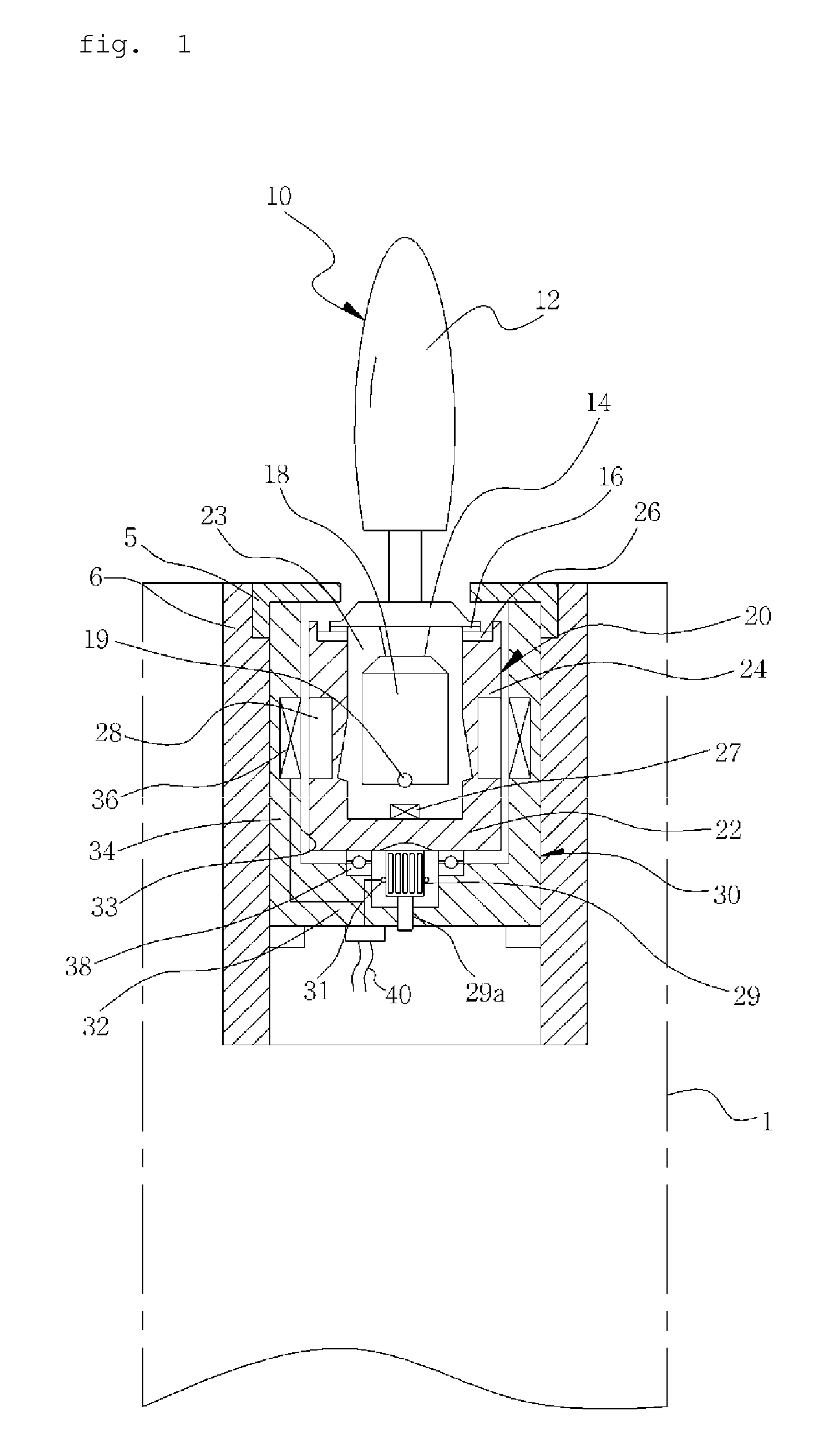
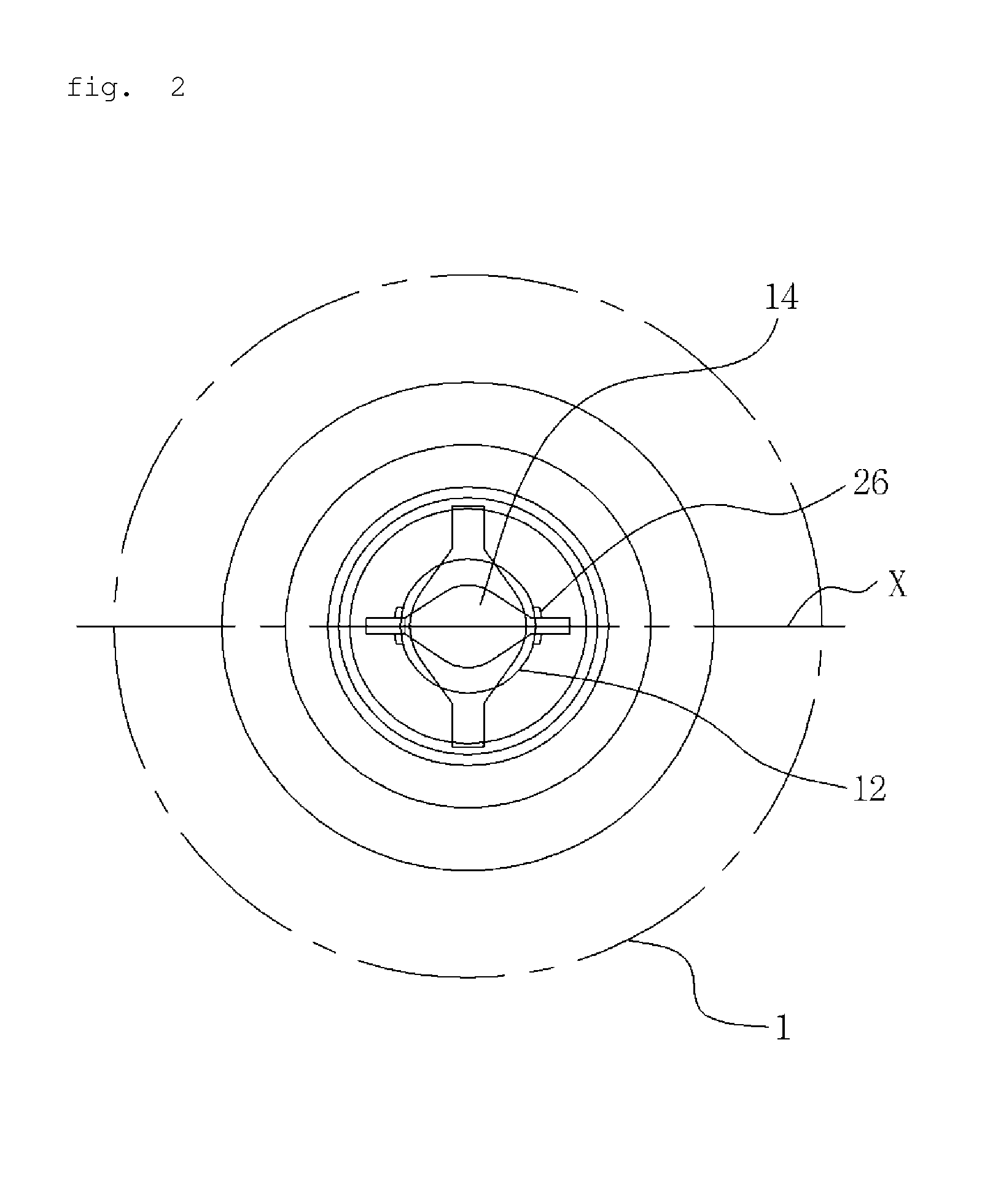
[0031]As shown in FIGS. 1, 2 and 5, an electric candle according to an embodiment of the present invention includes: a lamp unit 10 which has a lamp 12 held by a conductive wire 16 of a wing 14 and emitting light using electricity supplied thereto, and performs a pendulating motion by a weight 18 provided in a lower part thereof; a rotator 20 which receives the wing 14 therein and is electrically connected to the conductive wire 16; and a rotator housing 30 which receives the rotator 20 therein, and induces a concentric rotation of the rotator 20 therein using an electromagnetic force.

[0032]Here, the conductive wire 16 is electrically connected to the lamp 12 aft...


PUM


Abstract

Disclosed is a portable electric candle having a lamp pendulating and rotating simultaneously, including: a lamp unit (10) having a lamp (12), a weight (18), and a permanent magnet (19), wherein the lamp unit (10) can perform a pendulating motion using both a magnetic force and a repulsive force and repeats the pendulating motion using a restoring force; a rotator (20) including a cylindrical base (22), an inner container body (24), a contact terminal (26), the electromagnet (27), a magnetized body (28), and a power supply terminal part (29); a rotator housing (30) for inducing a rotation of the rotator (20) therein; and a motion selecting switch (102) for selecting a motion of the lamp (12) so as to perform one of a rotating motion and a pendulating motion selectively or to perform both the rotating motion and the pendulating motion simultaneously.

Description

TECHNICAL FIELD[0001]The present invention relates, in general, to an electric candle having a lamp electrically operated to emit light and, more particularly, to a portable electric candle having a lamp able to pendulate and rotate simultaneously, which is controlled to induce a pendulating motion of the lamp and to induce the lamp to rotate separately from or simultaneously with the pendulating motion, and in which the brightness and color of light can be changed and a preset operating time can be adjusted.BACKGROUND ART[0002]A candle made of a flammable solid material, such as paraffin, cannot continuously give light for a lengthy period time, requires careful handling and may cause a fire. Thus, electric candles that can be easily and safely turned on or turned off without causing a fire have been proposed and are used.[0003]An example of technologies relating to the present invention may be referred to Korean Utility Registration No. 20-0248825. This technology provides an elec...

Claims


Application Information

Patent Timeline
Patent Type & Authority Patents(United States)
IPC IPC(8): F21L4/04F21S10/04F21S6/00F21V14/02F21L4/08F21W121/00F21Y101/02F21Y113/00
CPCF21L4/04F21L4/08F21S6/001F21S10/046F21V14/02F21W2121/00F21Y2101/02F21Y2113/005F21Y2115/10F21Y2113/13F21L2/00
Inventor LEE, CHONG CEUL
Owner LEE CHONG CEUL
Learn More