Check patentability & draft patents in minutes with Patsnap Eureka AI!

Locomotive blue light reverser key

a reverser key and locomotive technology, applied in the field of rail safety, can solve the problems of serious injury to a railroad employee, locomotive operators will not be able to accidentally move the train, and locomotive operators will not see the blue signal

Active Publication Date: 2015-10-13
JURISLABS
View PDF12 Cites 1 Cited by
  • Summary
  • Abstract
  • Description
  • Claims
  • Application Information

AI Technical Summary

Benefits of technology

The blue light reverser key effectively prevents accidental train movement during blue signal procedures by visually and electronically notifying operators, ensuring safety by maintaining the locomotive in a stationary state until the procedure is complete.

Problems solved by technology

Although the blue signals may notify railroad employees and locomotive operators, there is a risk that the blue signals will not be visible to a locomotive operator.
Any movement of the train may result in serious injury to a railroad employee.
As a result, a train operator will not be able to accidentally move the train after the blue light reverser key is inserted into the reverser.

Method used


Image

  • Locomotive blue light reverser key
  • Locomotive blue light reverser key
  • Locomotive blue light reverser key

Examples


second embodiment

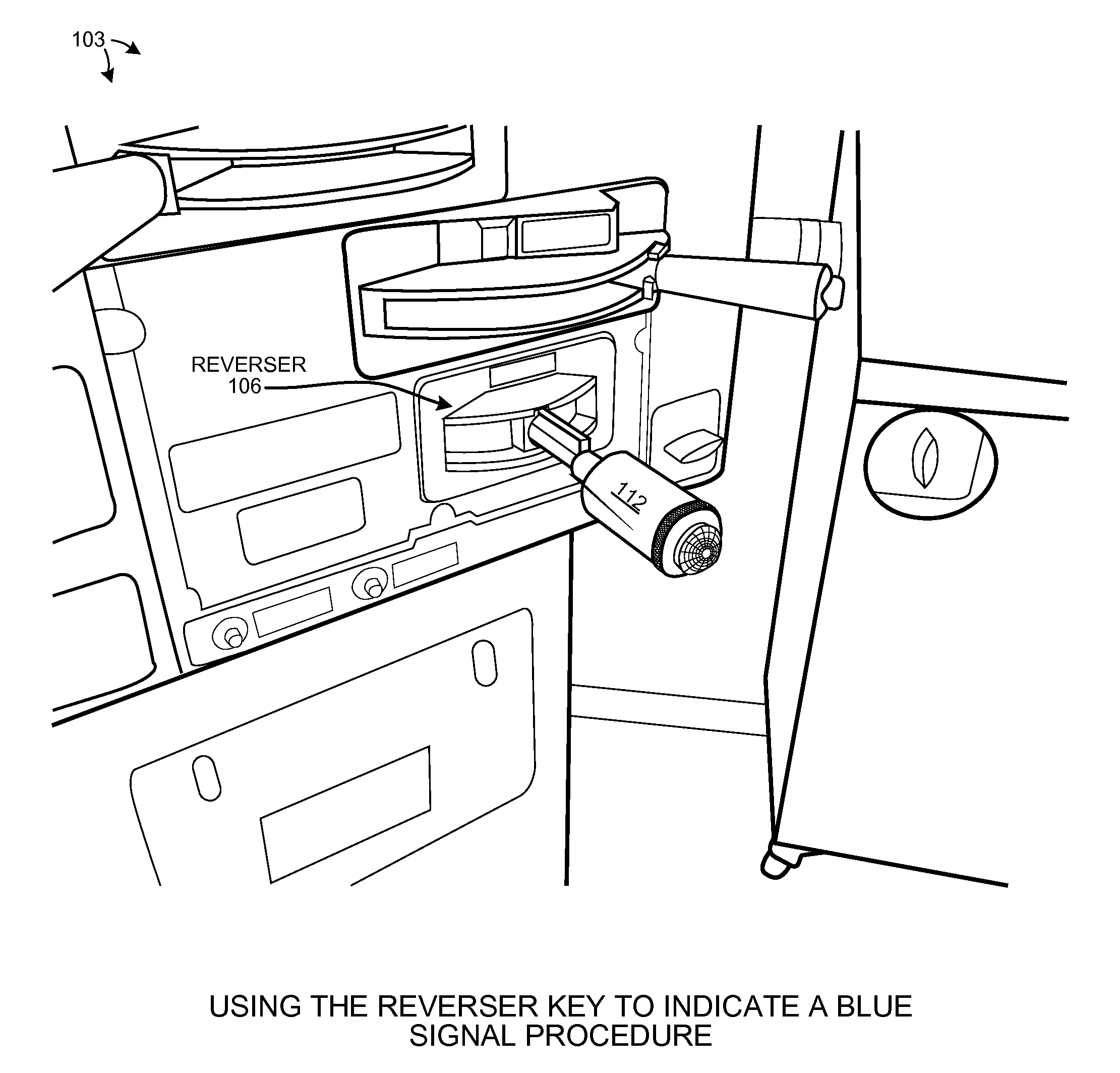
[0032]FIG. 7 is a diagram of a novel reverser key 200. Reverser key 200 includes a handle portion 201 and a shaft portion 202. Handle portion 201 includes a Light Emitting Diode (LED) 203, switch mechanism 204, battery 205, control circuitry 206, a Radio Frequency (RF) receiver 207, and an antenna 208. An RF signal 209 is received onto antenna 208. Receiver 207 detects the received RF signal 209 and causes control circuitry 206 to control switch mechanism 204 to activate LED 203. A lens 210 is tinted blue resulting in a blue light being emitted from reverser key 200. Utilization of reverser key 200 permits a railroad employee to notify all locomotive operators of the blue signal. After the reverser key 200 is activated and emits a blue light, then the locomotive operators will be informed of the blue signal condition and will know to insert the reverser key 200 into the reverser 106 to prevent any movement of the train.

[0033]FIG. 8 is a diagram showing how several locomotive operato...

third embodiment

[0034]FIG. 9 is a diagram of a novel reverser key 300. Reverser key is similar to reverser key 112 in FIG. 2, except that reverser key 300 includes V-notch 301 that unlocks tripping mechanism within the reverser 106. Reverser key 300 is a fully functional train key and is usable by a locomotive operator to control the reverser 106 and drive the train forwards and backwards. Reverser key 300 includes handle portion 302 and shaft portion 303. Handle portion 302 contains electronic devices convenient for use by a locomotive operator. In this example, handle portion 302 comprises a Light Emitting Diode (LED) 304, a switch mechanism 305, and a battery 306. In this fashion, reverser key 300 has a dual use in that it functions as a train key to control the reverser 106 and also functions as a flashlight.

[0035]The handle portion 302 may include other electronic devices of utility to a locomotive operator. For example, handle portion 302 may include a Global Position System (GPS) module that...


PUM


Abstract

A locomotive blue light reverser key has a handle portion and a shaft portion that is connected to the handle portion. The handle portion includes a Light Emitting Diode (LED), a switch, a battery that powers the LED, and a blue tinted lens. The shaft portion is insertable into a reverser of a locomotive. During a blue signal procedure when the train is not permitted to move, a train operator uses the blue light reverser key to indicate the blue signal procedure is in effect. The train operator activates the LED on the handle portion and inserts the blue light reverser key into the reverser. The shaft portion does not engage any locking mechanism within the reverser, and the reverser key prevents the locomotive from moving forward or backward. The blue light emitted from the blue light reverser key also notifies other train operators of the blue signal procedure.

Description

CROSS REFERENCE TO RELATED APPLICATIONS[0001]This application is a continuation of, and claims the benefit under 35 U.S.C. §120 from, nonprovisional U.S. patent application Ser. No. 13 / 841,458, entitled “Locomotive Blue Light Reverser Key,” filed on Mar. 15, 2013. This application incorporates by reference nonprovisional U.S. patent application Ser. No. 13 / 841,458.TECHNICAL FIELD[0002]The described embodiments relate generally to railroad safety, and more particularly to devices for notifying locomotive operators of blue signal procedures.BACKGROUND INFORMATION[0003]Locomotives are operated by railroad controllers to operate on railways that extend throughout the continent. At times it is desirable to conduct certain procedures on the railroad that may require a locomotive to remain standing and not be moved until it is safe to do so. These procedures typically involve railroad employees conducting inspection of the railway, conducting safety tests, performing repairs, or working on...

Claims


Application Information

Patent Timeline
Patent Type & Authority Patents(United States)
IPC IPC(8): B61L15/00
CPCB61L15/009B61C17/12
Inventor SAMORA, CECIL A.
Owner JURISLABS
Features
  • R&D
  • Intellectual Property
  • Life Sciences
  • Materials
  • Tech Scout
  • Unparalleled Data Quality
  • Higher Quality Content
  • 60% Fewer Hallucinations
Learn More