
Method for de-embedding in network analysis

a network analysis and network analysis technology, applied in the direction of measuring devices, resistance/reactance/impedence, instruments, etc., can solve the problems of presenting unwanted errors in measurement, methods beyond even their general complexity, and most complex and varied calibration methods, so as to achieve less error-prone, less complicated and easy

Active Publication Date: 2015-11-24
TELEDYNE LECROY
View PDF4 Cites 140 Cited by
  • Summary
  • Abstract
  • Description
  • Claims
  • Application Information

AI Technical Summary

Benefits of technology

[0015]In particular, it is an object of the invention to provide an easier, less complicated and less error-prone manner for de-embedding.

Problems solved by technology

Despite their potential high quality, they present unwanted error in the measurement.
Calibration is the most complex and varied method.
There are many drawbacks, however, to these methods beyond even their general complexity.
One is the requirement for multiple measurements which can be time consuming and prone to error.
These are expensive and multiple, identical probe connections must be made to the substrate for the multiple measurements involved in the calibration.
The drawback here is again identifying the standard characteristics, but also maintaining the identical nature of the path characteristics.
De-embedding is mathematically complex but once this complexity is overcome, it presents other practical problems.
The drawback of de-embedding methods is that they still require knowledge of the characteristics of the fixture and probing elements which are often difficult to ascertain.
This method has the benefit of being easy to employ, but suffers from an inability to easily produce a full set of DUT s-parameters.
Since s-parameter measurements are made not only for qualitative and quantitative measurements of DUT quality but also for generation of complete device models, gating cannot generally satisfy the latter requirement.
Furthermore, gating methods generally do not account for a variety of effects.
For example, the time-domain separation of responses does not account for reflections that occur in the measurement due to the gated out portions.
A general problem that occurs with all of these methods is the maintenance of constant characteristics at the DUT measurement ports.
This is difficult to maintain.

Method used


Image

  • Method for de-embedding in network analysis
  • Method for de-embedding in network analysis
  • Method for de-embedding in network analysis

Examples


Embodiment Construction

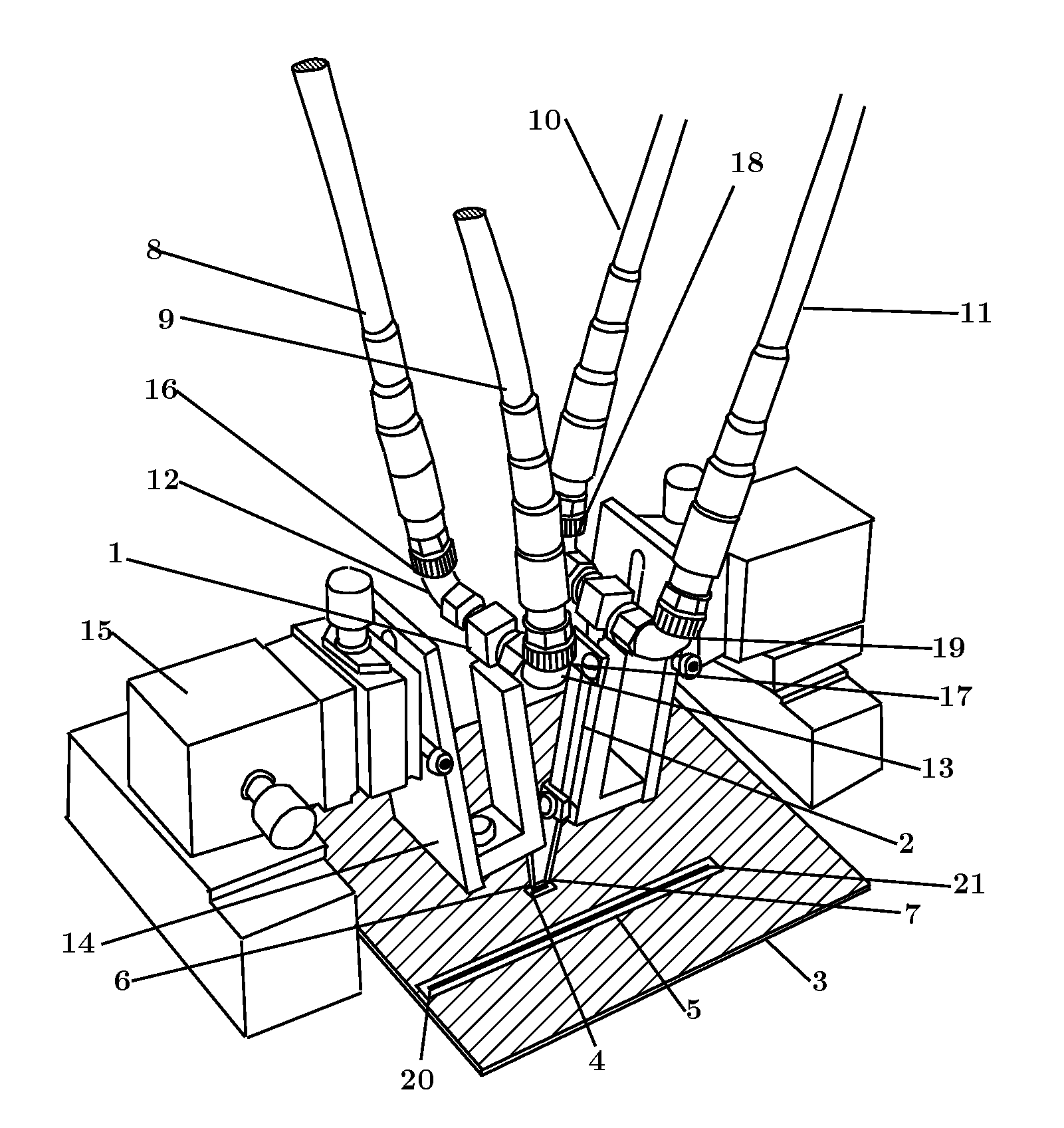
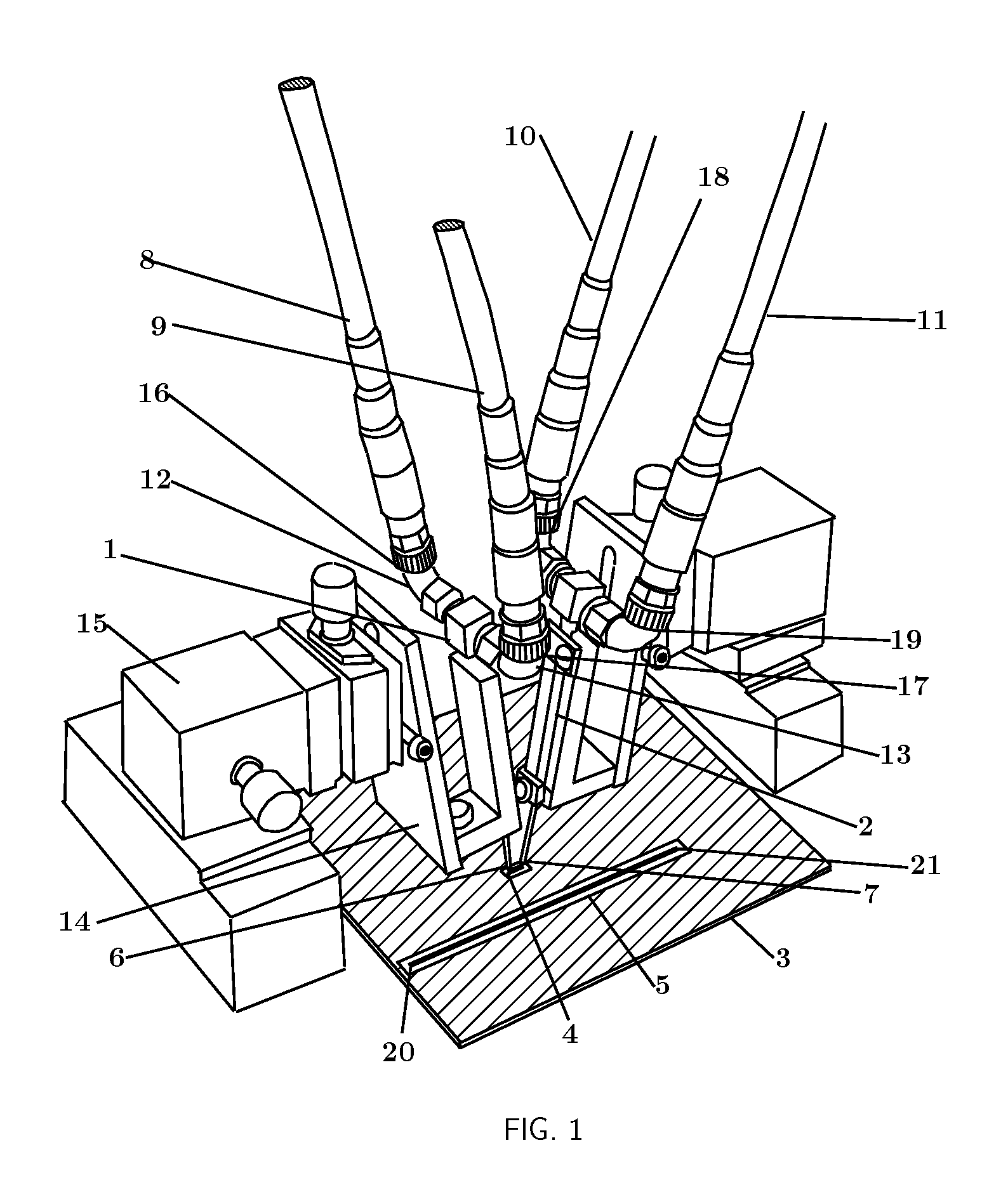
[0044]FIG. 1 shows an exemplary measurement arrangement in accordance with one or more embodiments of the invention. In this arrangement, a first probe [1] and a second probe [2] are shown probing a PCB trace. In this case the PCB [3] preferably contains two sets of traces; a 100 mil thru [4] and a three inch differential line [5]. FIG. 1 shows the probes [1] and [2] probing the 100 mil thru [4]. The probe tips, [6] and [7] are shown in detail probing the 100 mil thru [4] in FIG. 2. Considering probe 1 [1] (the arrangement for probe 2 [2] is similar), one sees cables [8] and [9] connected to right angle SMA adaptors [12] and [13] connected to the probe [1]. The probe [1] is held in a probe holder [14] which is positioned using a probe positioner [15]. In this particular case, the measurement is calibrated to the measurement reference planes [16], [17], [18] and [19] which are coaxial planes at the ends of the cables [8], [9], [10] and [11] respectively. The cables themselves are con...


PUM


Abstract

A method is provided for de-embedding fixtures and / or probes from measurements of devices where probes and fixtures are connected between the ports of a network analysis instrument and a device-under-test.

Description

FIELD OF THE INVENTION[0001]The present invention relates in general to network analysis and network device measurements. More specifically, one or more embodiments relate to measurements of a device under test (DUT) whereby the measurement instrument connection to the DUT is made utilizing fixtures or probes whose effects it is desirable to remove.BACKGROUND OF THE INVENTION[0002]Network analyzers are instruments that characterize networks. The characterization result is known to those of ordinary skill in the art and are based on conventions that define how the network will perform under various conditions. In signal integrity applications, the common network parameters in use are scattering parameters, or s-parameters. S-parameters define port to port relationships in a network when the network is driven by a source whose impedance is set to the reference impedance and all other ports are terminated in that same reference impedance. This convention allows scattering parameters to...

Claims


Application Information

Patent Timeline
Patent Type & Authority Patents(United States)
IPC IPC(8): G01R31/00G01R35/00G01R27/28
CPCG01R35/005G01R27/28H04Q2213/1316
Inventor PUPALAIKIS, PETER J.
Owner TELEDYNE LECROY
Learn More