Light source module, light source module driving circuit and driving method

a technology of light source modules and driving circuits, applied in the field of display driving, can solve the problems of increasing the workload of test, not being able to properly test the product and adjust the circuit, and complicated control of the whole driving circuit, so as to achieve convenient and reliable control

Active Publication Date: 2015-12-01
TCL CHINA STAR OPTOELECTRONICS TECH CO LTD
View PDF1 Cites 2 Cited by
  • Summary
  • Abstract
  • Description
  • Claims
  • Application Information

AI Technical Summary

Benefits of technology

[0007]The technical issue to be solved by the present invention is to provide a light source module, a driving circuit and a driving method of the light source module, which can make the driving circuit of the light source module get the input voltage to generate the enable signal and the dimming signal. Therefore, it makes the light source module work normally.
[0021]The benefits of the present invention are as follows. Differing from the situation of the prior art, the present invention converts the input voltage into the enable signal and the dimming signal through connecting the control signal generating circuit of the input voltage, which allows the input voltage, instead of the external control, converting to the enable signal and the dimming signal without the external controlling enable signal and dimming signal. Therefore, it only needs to provide external input voltage to control the light source module in operation, which makes the control more convenient and reliable.

Problems solved by technology

Thus, in the product design and experiment validation stage, the control of the whole driving circuit is more complicate.
It is not proper to test the product and adjust the circuit.
And when the external enable signal ENA and diming signal PWM are disturbed, the whole circuit will not work normally, which will increase the workload of the test and reduce the working efficiency.

Method used


Image

  • Light source module, light source module driving circuit and driving method
  • Light source module, light source module driving circuit and driving method
  • Light source module, light source module driving circuit and driving method

Examples


Embodiment Construction

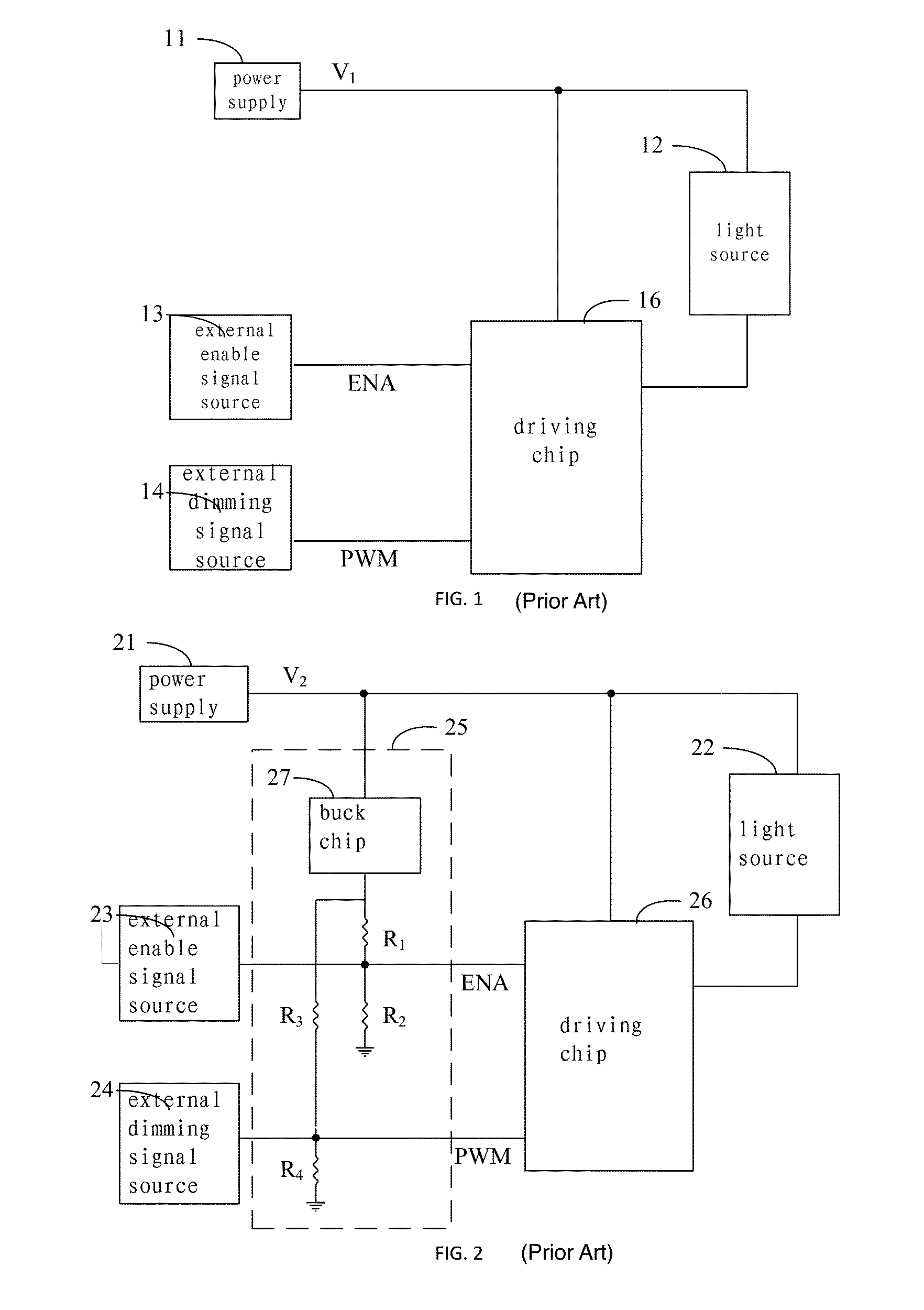
[0026]Referring to FIG. 2, FIG. 2 is a schematic diagram of the light source module according to the first embodiment of the present invention. The light source module driving circuit according to the first embodiment comprises a power supply 21, a control signal generating circuit 25, and a driving chip 26.

[0027]The power supply 21 provides the input voltage V2. The power supply 21 generally is the external power supply 21, which can be transferred through the commercial electricity or batteries.

[0028]The control signal generating circuit 25 is inputs the input voltage V2 provided from the power supply 21 and outputs an enable signal ENA and a dimming signal PWM. Generally, the input voltage V2 is higher than the voltage of the enable signal ENA and the dimming signal PWM. The input voltage V2 is generally 24V, while the voltages of the enable signal ENA and the dimming signal PWM are generally 3.3V, Therefore, in the present embodiment, the control signal generating circuit 25 is ...


PUM


Abstract

The present invention discloses a light source module, a light source module driving circuit and a driving method. The driving circuit comprises: a power supply, which provides input voltage; a control signal generating circuit, which inputs the input voltage provided from the power supply and outputs an enable signal and a dimming signal; a driving chip, which is connected with the power supply and connected to the enable signal and the dimming signal output from the control signal generating circuit, driving the light source of the light source module according to the enable signal and the dimming signal. Through the above way, the present invention utilizes the input voltage to generate the enable signal and the dimming signal. Therefore, it only needs to provide external input voltage to control the light source module in operation, which makes the control more convenient and reliable.

Description

BACKGROUND OF THE INVENTION[0001]1. Field of the Invention[0002]The present invention relates to the field of display driving, and in particular to a light source module, a light source module driving circuit and a driving method.[0003]2. The Related Arts[0004]Light source module is one of the necessary components in the liquid display module, which is used to provide the required light source of the liquid display panel.[0005]At present, LED light source module is the most popular light source module, as shown in FIG. 1. The present driving circuit of the LED light source module requires three external signals: an input voltage V1, an enable signal ENA, and a dimming signal PWM. Wherein, the input voltage V1, the enable signal ENA, and the dimming signal PWM are respectively connected to the power supply terminal, the enable control terminal, and the input terminal of the dimming signal of the driving chip 16. The input voltage V1 provides the power for the light source module, the...

Claims


Application Information

Patent Timeline
Patent Type & Authority Patents(United States)
IPC IPC(8): H05B33/08H05B44/00
CPCH05B33/0851H05B45/10
Inventor ZHANG, HUA
Owner TCL CHINA STAR OPTOELECTRONICS TECH CO LTD
Why Eureka
Try Eureka