Double-wrap brake band assembly

a brake band and double-wrap technology, applied in the direction of friction lining, gearing control, mechanical equipment, etc., can solve the problems of affecting the smooth operation of the gear change operation, affecting the operation of the gear change, so as to reduce the shock caused by the gear change

Inactive Publication Date: 2006-07-13
NSK WARNER
View PDF9 Cites 0 Cited by
  • Summary
  • Abstract
  • Description
  • Claims
  • Application Information

AI Technical Summary

Benefits of technology

[0027] According to the double-wrap band brake assembly of the present invention, it is preferable that the dynamic friction coefficient between the brake band and the rotating member at the beginning of the braking is decreased to realize a smooth braking operation and, when it is employed in an automatic transmission, a shock caused by gear change can be reduced.

Problems solved by technology

Incidentally, when the conventional double-wrap band brake assembly is used to brake a rotation element or the like of an automatic transmission, it sometimes becomes a hindrance to a smooth gear change operation.
However, in the double-wrap band brake assembly, a working stroke of the apply pin 23 is large, which results in a deteriorated response performance and a large torque capacity.
As a result, it is very difficult to control a servo pressure and a servo working amount.
However, if the servo pressure and the servo working amount fluctuate, the brake is applied with a little or no sliding amount so as to produce a great transmission shock.
As a result, it becomes difficult to detect a brake starting point of the double-wrap band brake assembly, so that driving control of another transmission element of the automatic transmission can not be smoothly effected.

Method used


Image

  • Double-wrap brake band assembly
  • Double-wrap brake band assembly
  • Double-wrap brake band assembly

Examples


first embodiment

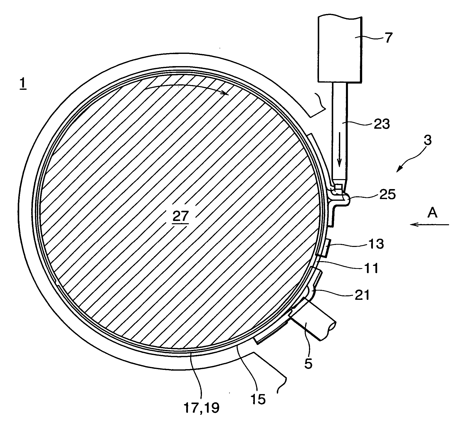
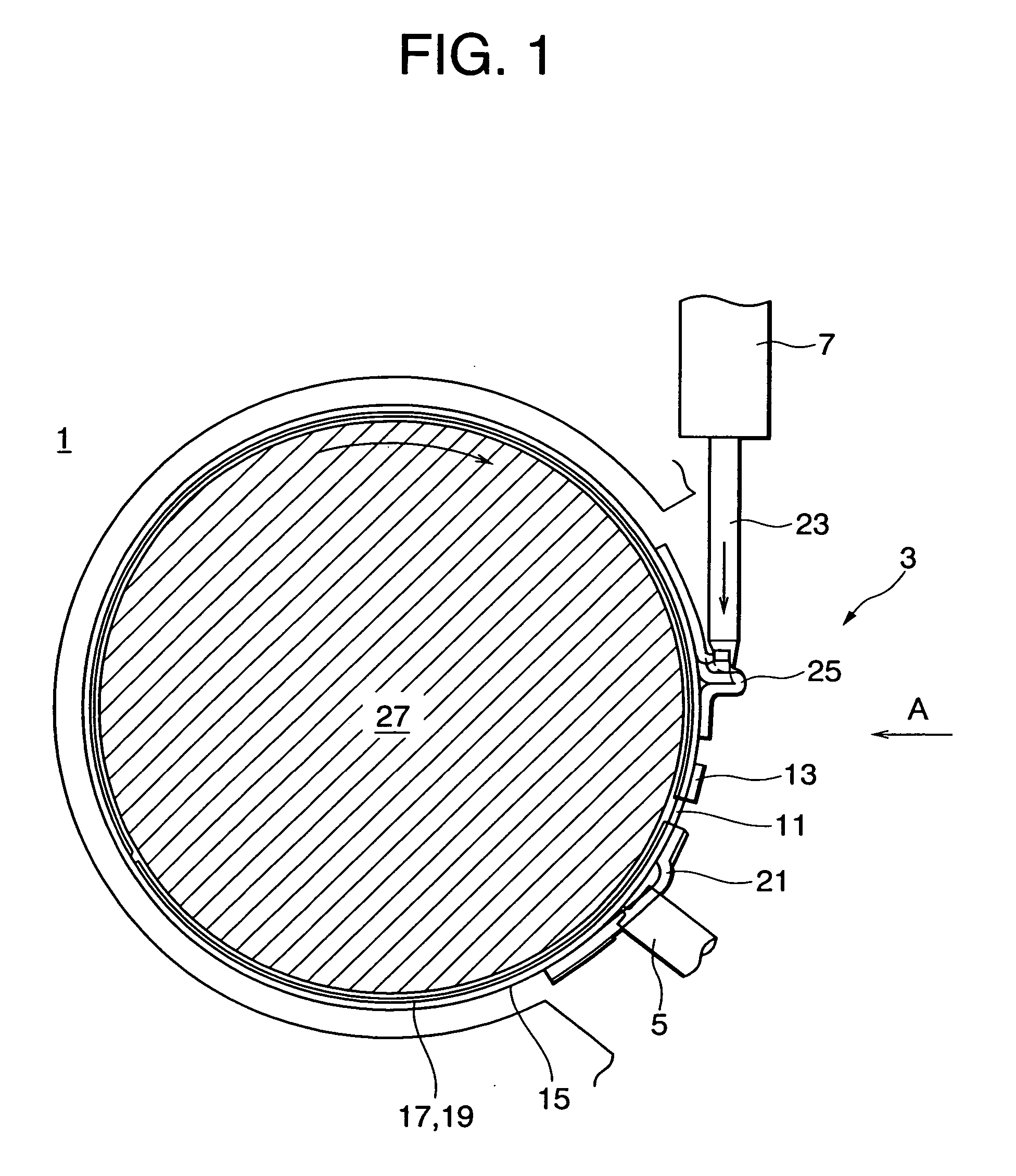
[0050]FIG. 1 is a side view for showing a double-wrap band brake assembly according to the present invention, FIG. 2 is a view seen from the arrow A in FIG. 1 (view seen from the front thereof), and FIG. 3 is a developed diagram of the double-wrap brake band, seen from the friction surface side. As seen from these drawings, the double-wrap band brake assembly of the present embodiment is comprised of a main body casing (transmission casing) 1, a double-wrap brake band 3 set inside the main body casing 1, an anchor pin 5 for securing the double-wrap brake band 3 to the main body casing 1, and an actuator 7 for driving the double-wrap brake band 3.

[0051] The double-wrap brake band 3 is mainly comprised of an annular middle band 11, and a pair of annular outer bands 15 which are welded to the middle band 11 through a coupling plate 13 in a state that the respective free ends thereof are opposed to the free end of the middle band 11. Frictional materials 17 and 19 are attached to the in...

second embodiment

[0057] In the second embodiment, it is possible to arbitrarily adjust a change in the dynamic friction coefficient between the double-wrap brake band 3 and the drum 27 by properly setting an angle α of the slanting surface 41 shown in FIG. 10 (an enlarged view of the portion B in FIG. 7) and an angle β of the corner portion 53 shown in FIG. 11 (an enlarged view of the portion C in FIG. 7). For this reason, when a torque capacity of the double-wrap band brake assembly is variously changed or the time required for this ratio to reach 100% is varied, such situation can be coped with the same assembly.

[0058] In the second embodiment, it is desirable that the angle α of the slanting surface 41 is within a range from 0.01° to 30°. The reason for this is that, when the angle α is 0.01° or smaller, it becomes very difficult to manufacture the double-wrap brake band 3 and also it becomes inevitable that the function of forming an oil film is gradually lost due to abrasion, or the like, cause...

third embodiment

[0060] Since the third embodiment employs such a structure, when the double-wrap brake band 3 which is driven by the apply pin 23 is constricted to be brought into sliding contact with the drum 27, an oil film 51 is formed on the thin surface 61 by an automatic transmission oil (ATF) existing between the thin surface 61 and the drum 27, as shown in FIG. 16. On the thick surface 63, the surface pressure around the oil reservoir 65 rises so that the dynamic friction coefficient is increased, thereby removing the oil film 51. Thus, the thick surface 63 is engaged with the drum 27 by the self engagement effect comparatively rapidly while no engagement is performed on the thin surface 61 until the oil film 51 between the surface 61 and the drum 27 is removed. As a result, as indicated by the solid line in FIG. 4, the dynamic friction coefficient between the double-wrap brake band 3 and the drum 27 rises in a short time and thereafter is kept substantially at the same level. Thus, the bra...


PUM


Abstract

A double-wrap band brake assembly to be used for braking a rotating member fitted in a double-wrap brake band, which double-wrap brake band comprises an annular middle band with a friction surface formed on the inner periphery thereof, a pair of annular outer bands which are coupled to the middle band in a state that the respective free ends thereof are opposed to the free end of the middle band, and which respectively have friction surfaces on the inner peripheries, an anchor bracket secured to the working end of either one of the middle band and the outer bands and latched to the main body casing, and an apply bracket secured to the working end of the other of the middle band and the outer bands for receiving a force in the direction of constriction of the middle band and the outer bands from an actuator. At least one of the middle band and the outer bands is provided with a first friction surface which is brought into sliding contact with the rotating member with a first dynamic friction coefficient at the beginning of the braking and a second friction surface which is brought into sliding contact with the rotating member with a second dynamic friction coefficient larger than the first dynamic friction coefficient at the beginning of the braking.

Description

[0001] This application claims the benefit of Japanese Patent application No. 2002-351606 which is hereby incorporated by reference. BACKGROUND OF THE INVENTION [0002] 1. Field of the Invention [0003] The present invention relates to a double-wrap brake band assembly which is used in an automatic transmission, or the like, for a car, and to a technology for facilitating and securing a braking control. [0004] 2. Related Background Art [0005] A band brake apparatus is widely used for braking a transmission element or rotation element in an automatic transmission for a car or in a general industrial machine. A band brake apparatus generally comprises a brake band which is formed by attaching a frictional material to the inner peripheral surface of one steel plate in an annular form. This brake band is constricted by an actuator to fasten a transmission element or a rotation element disposed on the inner side thereof to apply the brake. Therefore, recently, in order to reduce the workin...

Claims


Application Information

Patent Timeline
Patent Type & Authority Applications(United States)
IPC IPC(8): F16D51/00F16D65/06F16D49/02F16D49/08F16D69/00F16D69/04F16H63/30
CPCF16D49/02F16D49/20F16D65/06F16D65/065F16D69/0416F16D2069/003F16H63/3003
Inventor FUJII, TAMOTSUGU, XIAOMINGTAKABAYASHI, HIDEAKITANAKA, OSAMU
Owner NSK WARNER
Why Eureka
Try Eureka