
Power supply circuit for driving LED lamp and power supply method, and primary-side control circuit of flyback transformer
a technology of power supply circuit and power supply method, which is applied in the direction of process and machine control, electric variable regulation, instruments, etc., can solve the problems of flicker, color change, and inability to meet the design or cost requirements of ac-dc converters with the aforementioned two-stage structure for indoor electric lights, and achieves stable link voltage and reduces the output current of the flyback converter
- Summary
- Abstract
- Description
- Claims
- Application Information
AI Technical Summary
Benefits of technology
Problems solved by technology
Method used
Image

Examples
Embodiment Construction
[0027]Hereafter, exemplary embodiments of the present invention will be described in detail with reference to the accompanying drawings.
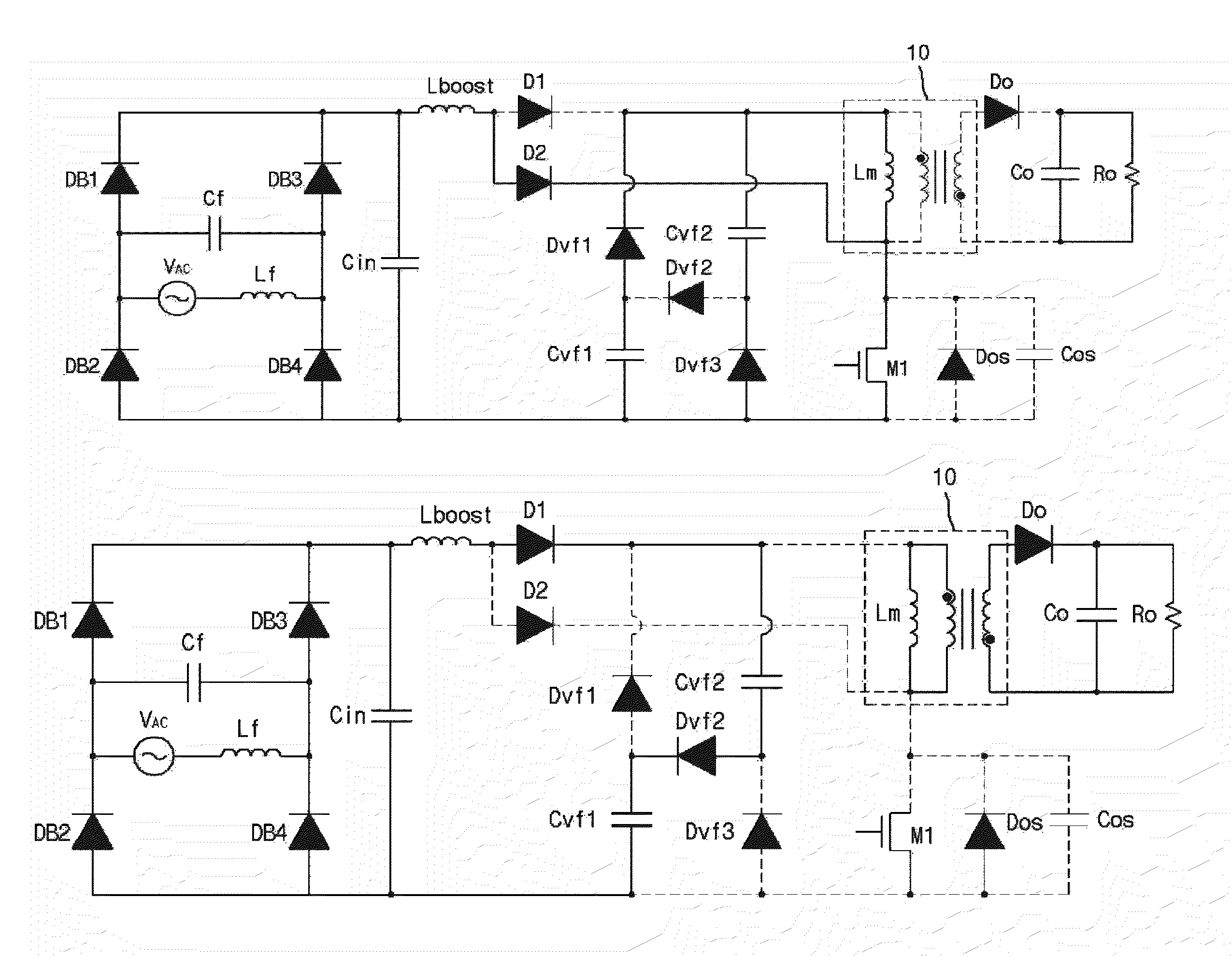
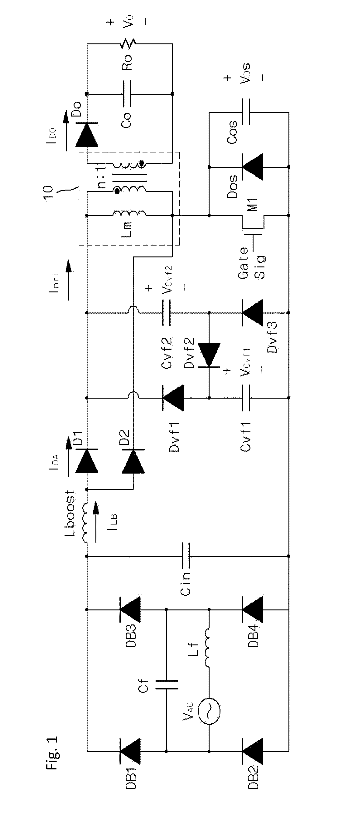
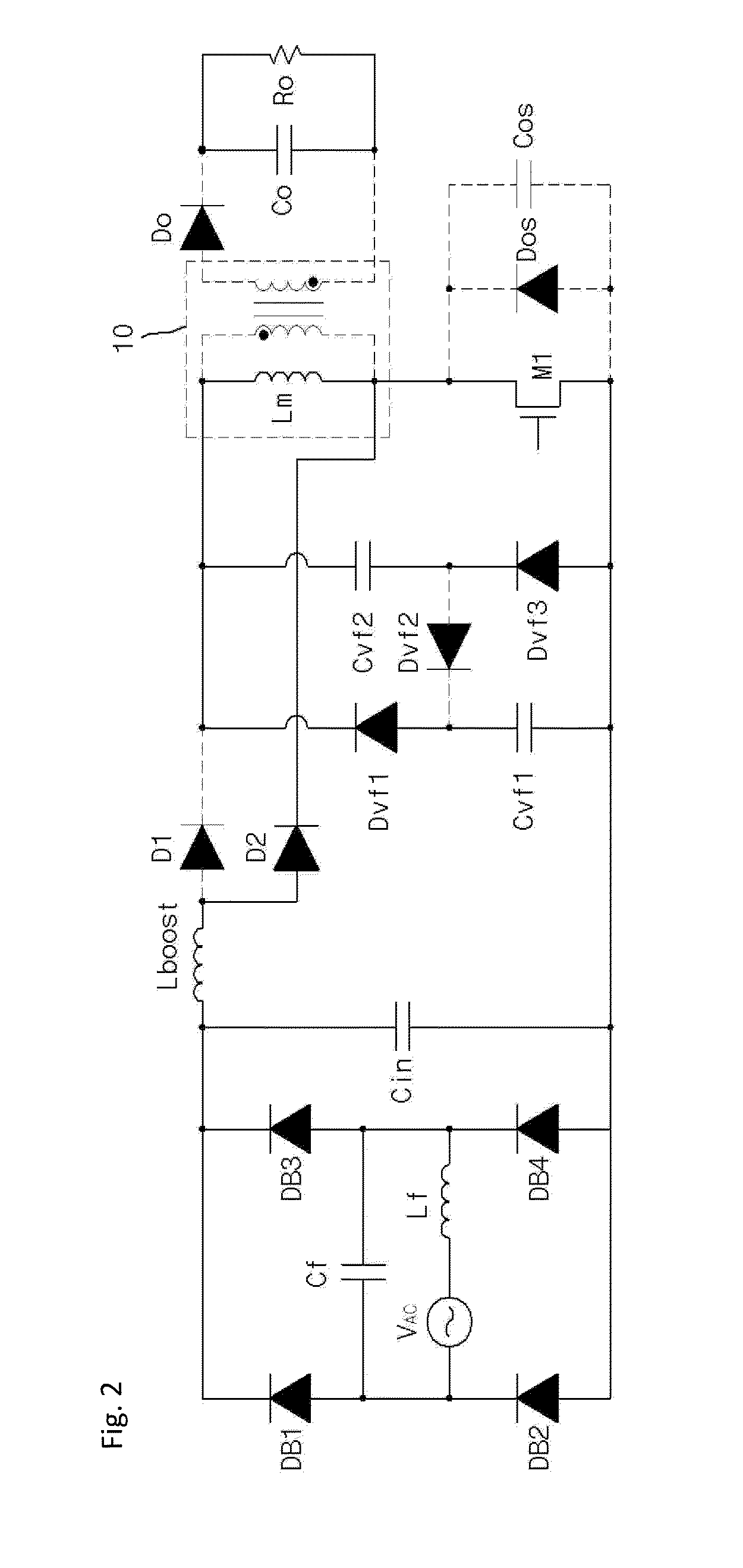
[0028]An embodiment according to the present invention may have a configuration as illustrated in FIG. 1. The embodiment of FIG. 1 has a two-stage structure including a boost power factor correction converter that performs first power factor correction with a first DCM and provides a boost current (ILB) and a flyback Dc-DC converter that performs second power factor correction with a second DCM.
[0029]The boost power factor correction converter includes a rectification circuit that outputs a rectified voltage and a boost inductor (Lboost) that receives the output of the rectification circuit and provides the boost current (ILB).
[0030]The rectification circuit includes an AC power source (VAC), a filter inductor (Lf) serially connected to the AC power source (VAC), a filter capacitor (Cf) connected in parallel with the AC power source (VAC) and the fi...
PUM
 Abstract
Description
Claims
Application Information