Direct current electric starter solenoid manual activation device

a solenoid and electric starter technology, applied in the direction of engine starters, electric motor starters, machines/engines, etc., can solve problems such as difficulty in activating the starter motor

Active Publication Date: 2016-06-07
MCNABB KEVIN LLOYD
View PDF46 Cites 2 Cited by
  • Summary
  • Abstract
  • Description
  • Claims
  • Application Information

AI Technical Summary

Problems solved by technology

However, when the battery on the vehicle is dead or there is some other starter malfunction, it may very difficult to activate the starter motor.

Method used


Image

  • Direct current electric starter solenoid manual activation device
  • Direct current electric starter solenoid manual activation device
  • Direct current electric starter solenoid manual activation device

Examples


Embodiment Construction

[0010]The following detailed description is of the best currently contemplated modes of carrying out exemplary embodiments of the invention. The description is not to be taken in a limiting sense, but is made merely for the purpose of illustrating the general principles of the invention, since the scope of the invention is best defined by the appended claims.

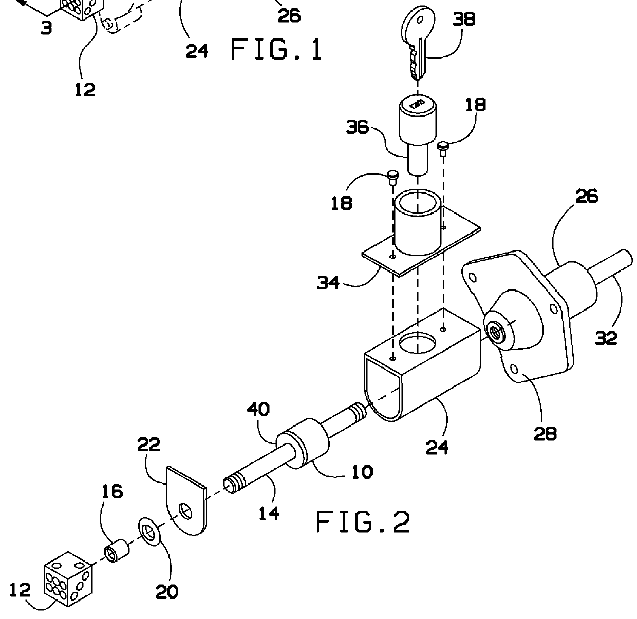
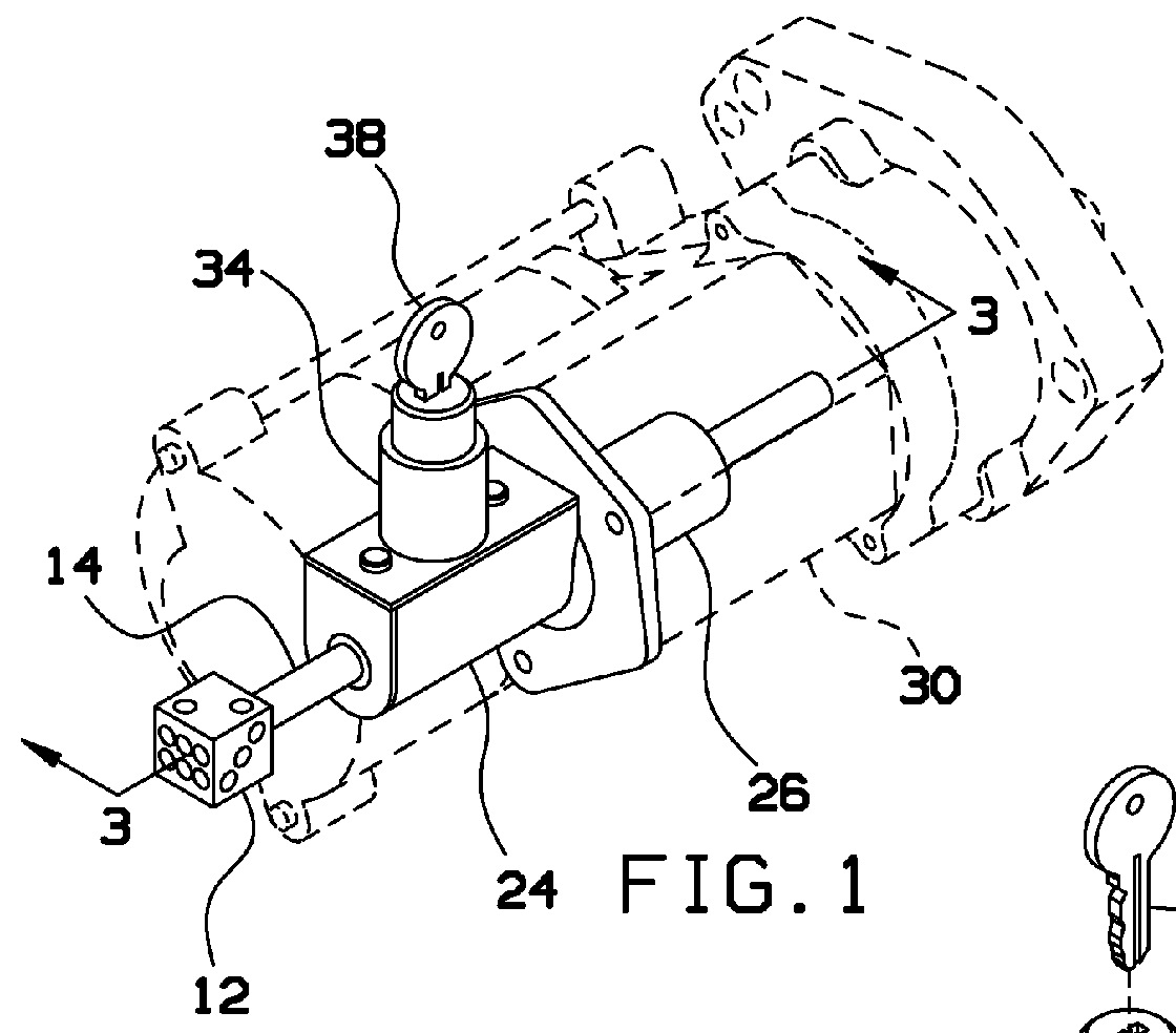
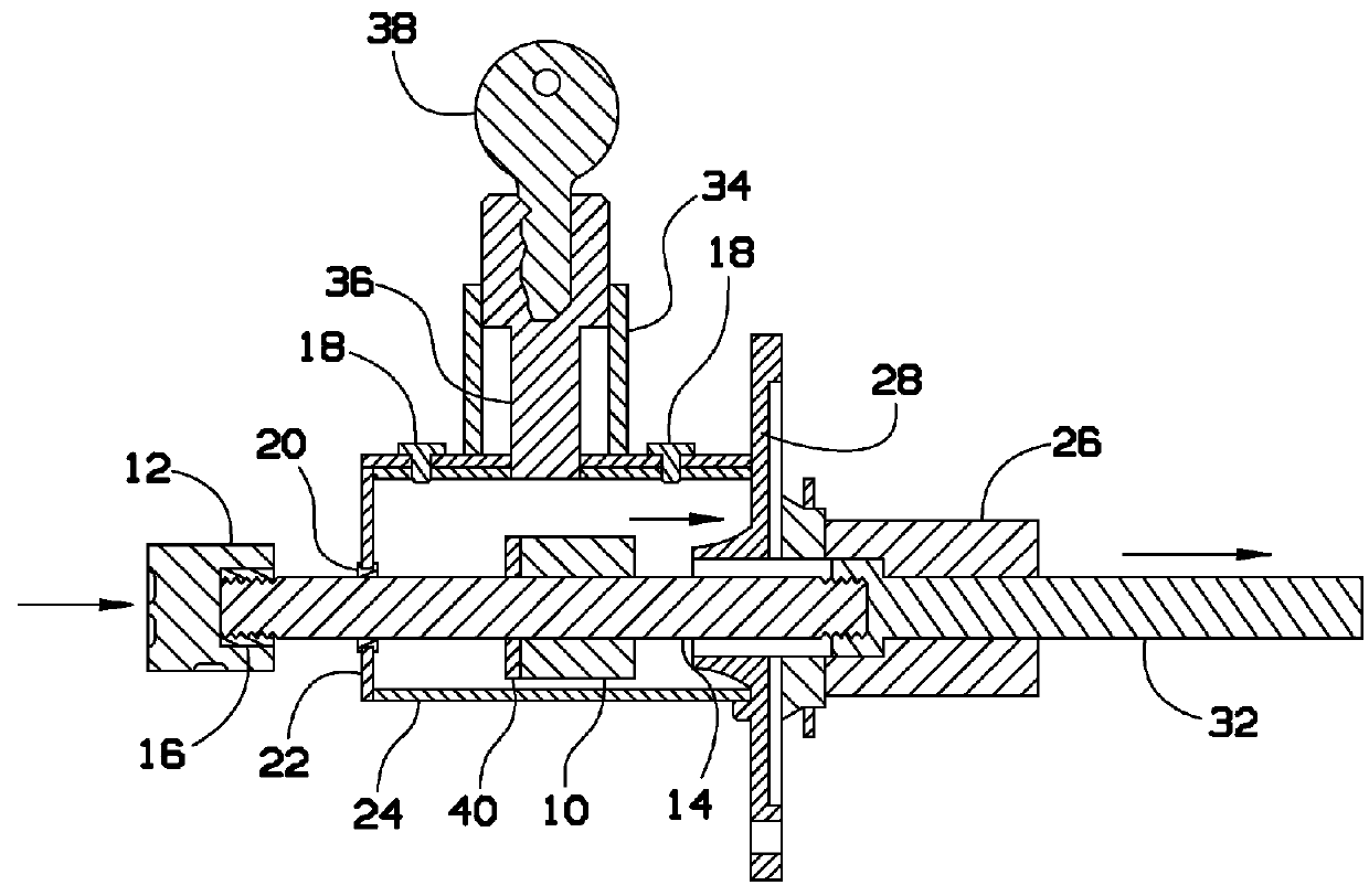
[0011]Broadly, an embodiment of the present invention provides a manual activation device for activating a starter assembly. The present invention may include a push rod that is connected to a solenoid plunger. The starter may be activated manually by pushing the rod and thereby pushing the solenoid plunger into the gears. Therefore, if there is an electrical or mechanical malfunction with the starter or the vehicle, the push rod may be pushed in to start the vehicle.

[0012]The present invention may allow for manual engagement of a D / C starter solenoid on a combustion engine when the starter fails due to mechanical or electrical ...


PUM


Abstract

A manual activation device for activating a starter assembly. The present invention may include a push rod that is connected to a solenoid plunger. The starter may be activated manually by pushing the rod and thereby pushing the solenoid plunger into the gears. Therefore, if there is an electrical or mechanical malfunction with the starter or the vehicle, the push rod may be pushed in to start the vehicle.

Description

BACKGROUND OF THE INVENTION[0001]The present invention relates to a manual starter activation device and, more particularly, to a push rod that is connected to a solenoid plunger to manually activate the starter.[0002]The modern starter motor is either a permanent-magnet or a series-parallel wound direct current electric motor with a starter solenoid (similar to a relay) mounted on it. When current from the starting battery is applied to the solenoid, usually through a key-operated switch, the solenoid engages a lever that pushes out the drive pinion on the starter driveshaft and meshes the pinion with the starter ring gear on the flywheel of the engine. However, when the battery on the vehicle is dead or there is some other starter malfunction, it may very difficult to activate the starter motor.[0003]As can be seen, there is a need for a device for manually activating the starter motor.SUMMARY OF THE INVENTION[0004]In one aspect of the present invention, a device for manually acti...

Claims


Application Information

Patent Timeline
Patent Type & Authority Patents(United States)
IPC IPC(8): F02N11/00F02N11/10F02N15/06
CPCF02N11/00F02N11/101F02N15/068
Inventor MCNABB, KEVIN LLOYD
Owner MCNABB KEVIN LLOYD
Why Eureka
Try Eureka