Sensor device, in particular for use in a motor vehicle

a sensor device and motor vehicle technology, applied in the direction of measurement devices, fluid pressure measurement by mechanical elements, instruments, etc., can solve the problems of relatively complicated design of plug connections, expansion space to ensure the mobility of contacts, and reduce manufacturing costs. , the effect of simple contacting between the plug connection and the sensor elemen

Active Publication Date: 2016-06-07
ROBERT BOSCH GMBH
View PDF14 Cites 12 Cited by
  • Summary
  • Abstract
  • Description
  • Claims
  • Application Information

AI Technical Summary

Benefits of technology

[0003]Based on the prior art described above, the aim underlying the invention is to further develop a sensor device in such a manner that a particularly simple manufacturability of the contacting between the plug connections and the sensor element is facilitated while simultaneously favorable manufacturing costs and reliable electrical contacting are provided. This aim is met according to the invention by a sensor device by virtue of the fact that the electrical plug connections are arranged in a stationary manner in the housing in the region of the contacts with the electrical contact areas of the sensor element and that a support is formed between the sensor element and the housing in such a manner that the sensor element has three-point contact in the housing. In other words, this means that the plug connections are rigidly arranged or formed in the region of the electrical contacting with the sensor element which simplifies the design and arrangement of the plug connections. In addition, a defined electrical contacting of the sensor element to the plug connections is ensured by the three-point contact of the sensor element in the housing.
[0006]An embodiment is particularly preferred in which an elastic intermediate element is disposed between the housing cover and the sensor element. As a result, component tolerances can be compensated and a reliable electrical contact can be produced.
[0007]In particular when using the sensor device as a pressure sensor, provision can thereby be made for the sensor element to have a measurement surface which is surrounded by the intermediate element and is sealed towards the housing interior and for the housing cover to have a channel which connects the region of the measurement surface to the environment. A targeted air guidance is thereby facilitated through the channel towards the measurement surface by means of the intermediate element which surrounds the measurement surface in a sealing manner; thus enabling such a pressure sensor to operate particularly safely and reliably.
[0008]In order to facilitate a mounting of the housing element to the housing which is as simple and cost effective as possible and at the same time is particularly reliable by functional standards, it is furthermore proposed that the housing element be connected to the housing by means of a latching connection. Such a latching connection can be very easily implemented without additional auxiliary materials or joining elements (adhesives, screws).
[0010]The mounting process of the housing element to the housing can furthermore be safely and reliably implemented if guide elements are present for the correct angular mounting of the housing element to the housing. As a result, misalignments during mounting which can possibly incur damage to components are prevented.

Problems solved by technology

The design of such plug connections, which in the case of the German patent specification DE 10 2008 000 889 A1 comprise a curved shape in the region of the contacts and an expansion space to ensure the mobility of the contacts, is relatively complicated.

Method used


Image

  • Sensor device, in particular for use in a motor vehicle
  • Sensor device, in particular for use in a motor vehicle
  • Sensor device, in particular for use in a motor vehicle

Examples


Embodiment Construction

[0019]Identical components or components serving the same function are provided with the same reference numerals in the figures.

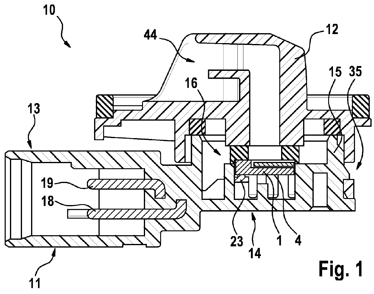
[0020]A sensor device 10 according to the invention is depicted in FIG. 1 as it is to be used as a pressure sensor in a motor vehicle. The invention is however not intended to be limited to pressure sensors for use in motor vehicles but can, if need be with corresponding adaptations or modifications, be applied to any other sensor devices.

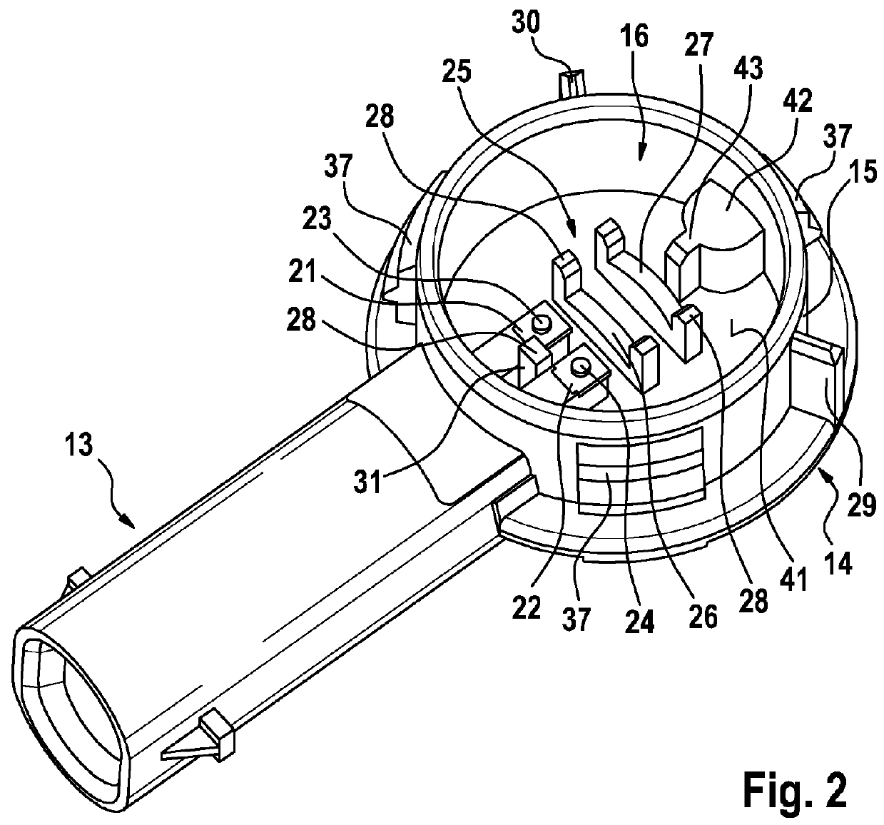
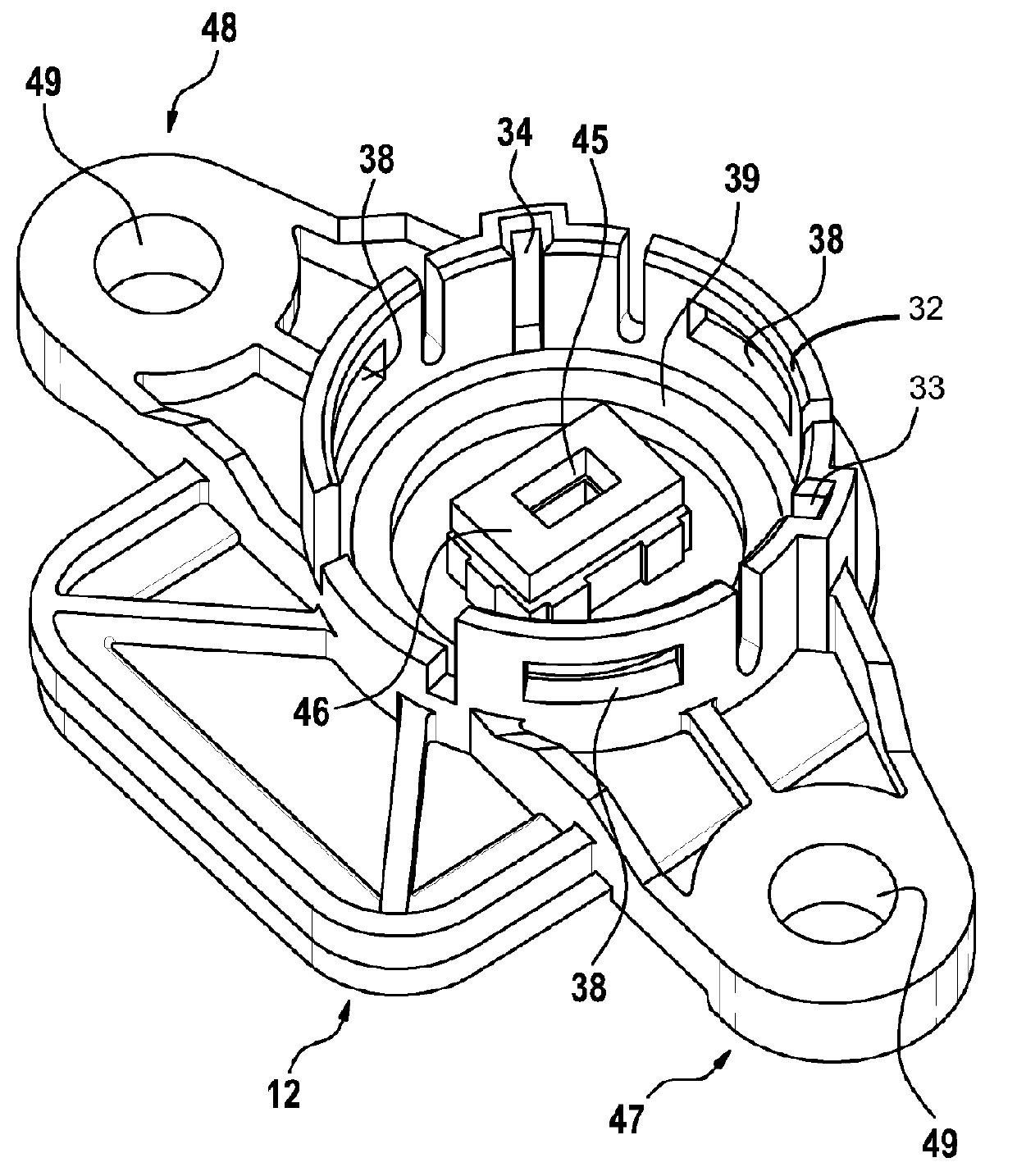
[0021]The sensor device 10 has a housing 11 in the shape of a housing bottom part which can be closed by means of a housing cover 12. As is particularly apparent in an overall view of both FIGS. 1 and 2, the housing 11 comprises an elongated plug connection region 13, which is adjoined by a receiving region 14 that is substantially of round configuration when viewed from above and serves to accomodate a sensor element 1 depicted in FIGS. 1, 4 and 5. The receiving region 14 has a circumferential wall 15 in the shape of a ci...


PUM

PropertyMeasurementUnit
forceaaaaaaaaaa
elasticaaaaaaaaaa
areasaaaaaaaaaa

Abstract

The invention relates to a sensor device (10), in particular for use in a motor vehicle, having a housing (11) for accommodating a sensor element (1), wherein the sensor element (1) has electrical contact areas (2, 3) which are connected to electrical plug connections (18, 19) arranged in the housing (11) in an electrically conductive manner in the region of contacts (23, 24) of the plug connections (18, 19), wherein a force is applied to the sensor element (1) for the purpose of making electrical contact with a housing element in the direction of the plug connections (18, 19). The invention provides for the electrical plug connections (18, 19) to be arranged in a stationary manner in the housing (11) in the region of the contacts (23, 24) with the electrical contact areas (2, 3) of the sensor element (1), and for a support to be formed between the sensor element (1) and the housing (11) in such a manner that the sensor element (1) has three-point contact in the housing (11).

Description

BACKGROUND OF THE INVENTION[0001]The invention relates to a sensor device, in particular for use in a motor vehicle having a housing for accommodating a sensor element, wherein the sensor element has electrical contact areas which are connected to electrical plug connections arranged in the housing in an electrically conductive manner in the region of contacts of the plug connections, wherein a force is applied to the sensor element for the purpose of making electrical contact with a housing element in the direction of the plug connections.[0002]Such a sensor device is disclosed by the German patent specification DE 10 2008 000 889 A1 of the applicant. The known sensor device, which is designed as a pressure sensor, has a housing for accommodating a sensor element. The sensor element is thereby of block-shaped design according to one embodiment and has contact areas, which are disposed on the bottom side of said sensor element so as to be integrated therein, for electrically contact...

Claims


Application Information

Patent Timeline
Patent Type & Authority Patents(United States)
IPC IPC(8): G01L7/00G01D11/24G01D11/30
CPCG01D11/245G01D11/30G01L19/143
Inventor HENZLER, STEPHANWOERNLE, WOLFGANGHERRMANN, ALEXANDERBERTSCH, BENJAMIN
Owner ROBERT BOSCH GMBH
Why Eureka
Try Eureka