Method and device for the serial production of a vehicle assembly, bearing unit, vehicle steering wheel and horn module for a steering wheel assembly and steering wheel assembly

a technology for steering wheel assemblies and steering wheels, which is applied in the direction of steering parts, vehicle components, pedestrian/occupant safety arrangements, etc., can solve the problems of increased manufacturing costs, increased manufacturing costs, and reduced production efficiency, so as to achieve accurate and simple positioning of horn modules, rapid and energy-saving softening, and high accuracy

Active Publication Date: 2016-06-14
TRW AUTOMOTIVE SAFETY SYST
View PDF22 Cites 6 Cited by
  • Summary
  • Abstract
  • Description
  • Claims
  • Application Information

AI Technical Summary

Benefits of technology

[0010]This method offers the advantage that an exact orientation of the components can take place despite the high manufacturing tolerances of the individual components.
[0043]For detecting the position of the support or the component the measuring system includes e.g. at least one laser. For simple positioning the positioning system comprises the afore-mentioned six-axis bench.

Problems solved by technology

The clearances required in the automotive industry are below the added-up manufacturing tolerances of the individual components, especially in the interior of a vehicle, however.
Higher accuracy of the components can only be achieved, however, by a substantially greater manufacturing effort.

Method used


Image

  • Method and device for the serial production of a vehicle assembly, bearing unit, vehicle steering wheel and horn module for a steering wheel assembly and steering wheel assembly
  • Method and device for the serial production of a vehicle assembly, bearing unit, vehicle steering wheel and horn module for a steering wheel assembly and steering wheel assembly
  • Method and device for the serial production of a vehicle assembly, bearing unit, vehicle steering wheel and horn module for a steering wheel assembly and steering wheel assembly

Examples


Embodiment Construction

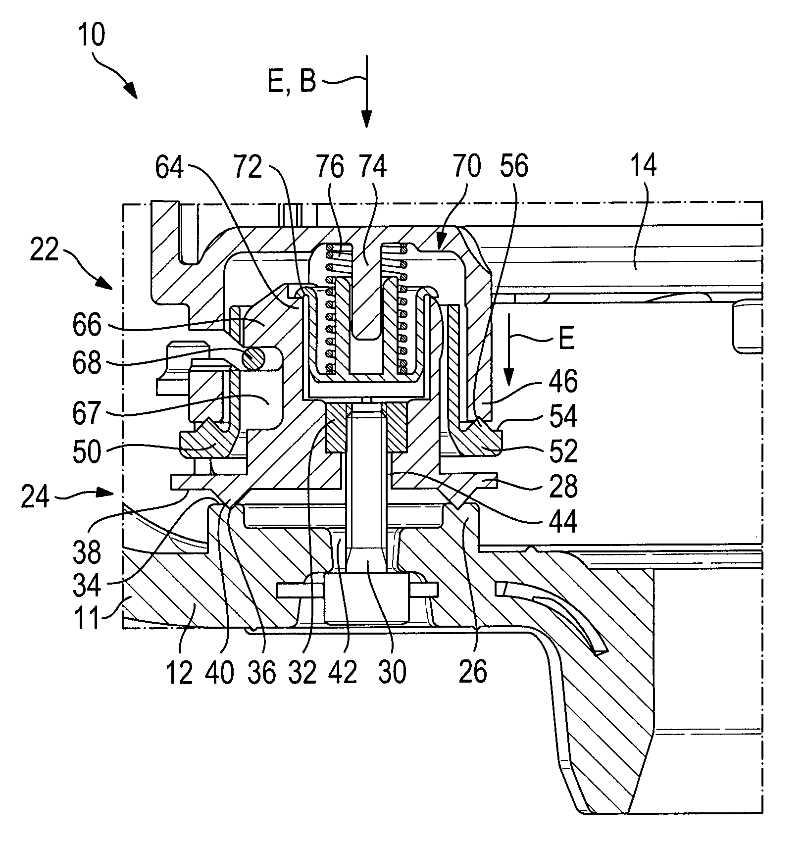
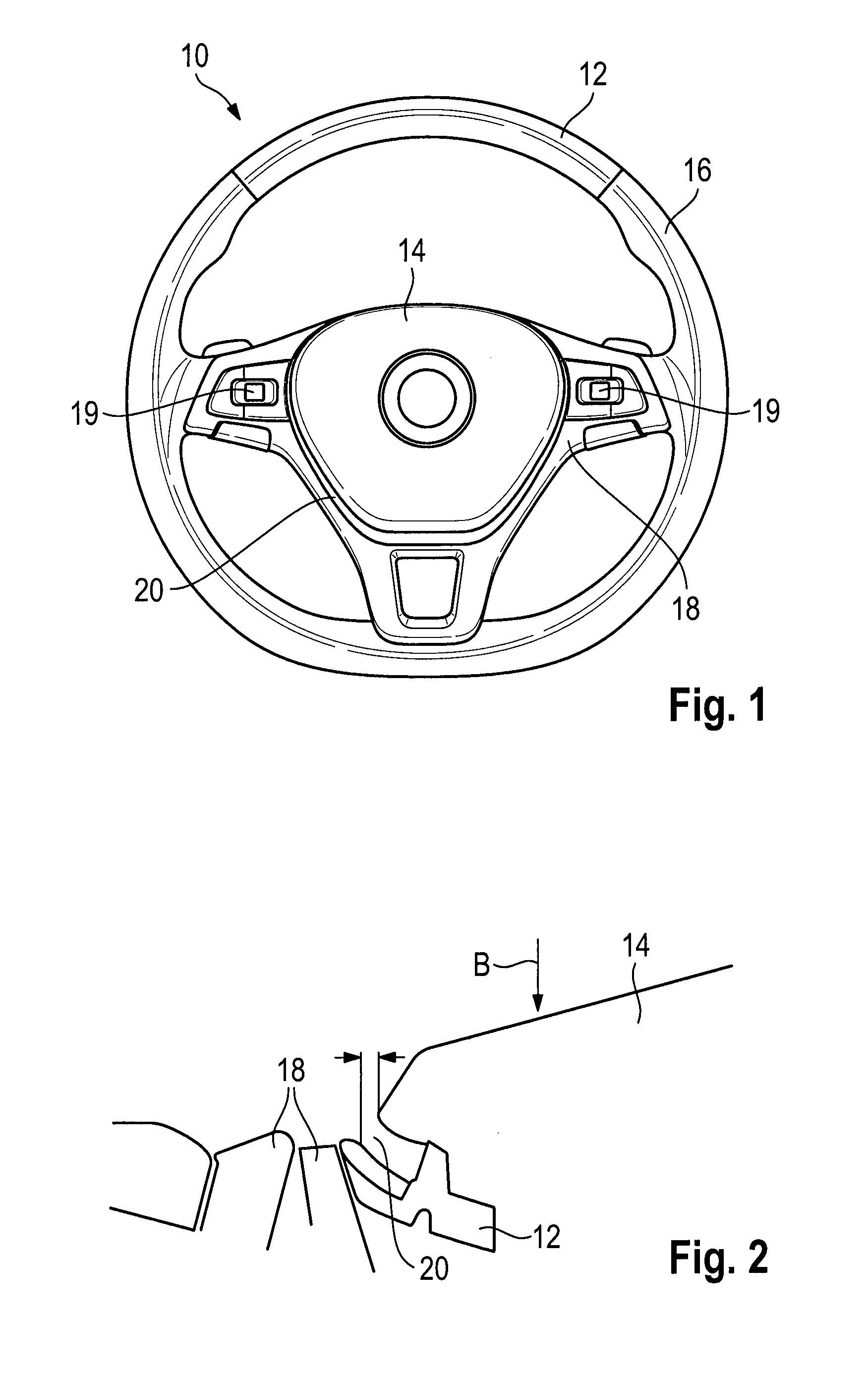
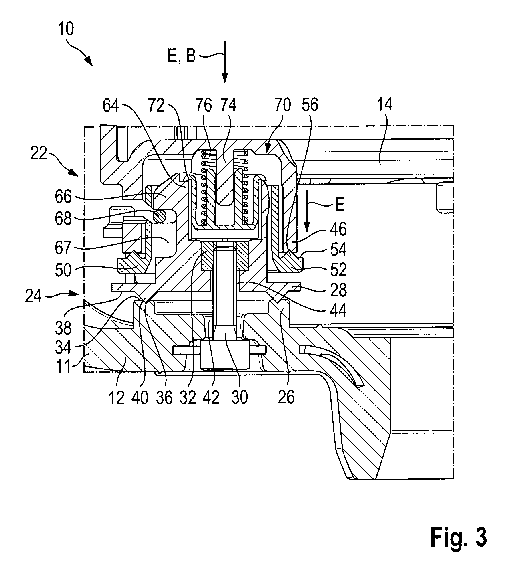
[0061]FIG. 1 illustrates a steering wheel assembly 10 comprising a vehicle steering wheel 12 as well as a horn module 14, more exactly an airbag module. The horn module 14 is movably fastened to the vehicle steering wheel 12 and can be forced in an actuating direction B against the vehicle steering wheel 12 to actuate the horn (cf. also FIG. 2). The vehicle steering wheel 12 includes a steering wheel skeleton 15, a foam material 16 as well as a cover 18 in which plural operating elements 19 are integrated. The vehicle steering wheel 12 constitutes a support and the horn module 14 constitutes a component to be fastened thereon. Consequently, when hereinafter the steering wheel and the module are mentioned, this is merely an example of a support and a component which is not to be understood to be limiting.

[0062]Between the cover 18 and the horn module 14 a clearance 20 is provided. It is intended, on the one hand, to ensure low-friction movement of the horn module 14 in the actuating ...


PUM

PropertyMeasurementUnit
areaaaaaaaaaaa
relative displacementaaaaaaaaaa
dimensionsaaaaaaaaaa

Abstract

A method for series production of a vehicle assembly, especially an interior assembly, including a vehicle-side support, especially a vehicle steering wheel (12), and a component to be fastened at the support, especially a horn module (14), wherein a module-side bearing unit (22) consisting of at least two bearing members (46, 50) is assigned to the component and / or a support-side bearing unit (24) consisting of at least two bearing members (26, 28) is assigned to the support, and wherein one of the bearing members (28, 50) of the respective bearing unit (22, 24) has a contact surface (34, 58) and the other one of the bearing members (26, 46) has at least one bearing surface (38, 54) includes the step of individually orientating the two bearing members (26, 28, 46, 50) of at least one bearing unit (22, 24) relative to each other as a function of the actual dimensions of the support installed and / or the component installed, fastening the two bearing members (26, 28, 46, 50) orientated relative to each other, and fastening the component to the support. The position of the support and the component relative to each other is defined by at least one bearing unit (22, 24).

Description

RELATED APPLICATIONS[0001]This application corresponds to PCT / EP2012 / 003850, filed Sep. 14, 2012, which claims the benefit of German Application Nos. 10 2011 113 351.1, filed Sep. 15, 2011 and 10 2012 002 722.2, filed Feb. 14, 2012, the subject matter, of which are incorporated herein by reference in their entirety.BACKGROUND OF THE INVENTION[0002]The invention relates to a method for series production of a vehicle assembly as well as an apparatus for carrying out said method. Furthermore, the invention relates to a bearing unit, a vehicle steering wheel and a horn module for such vehicle assembly as well as a steering wheel assembly.[0003]In a number of vehicle assemblies, especially in the vehicle interior, a component is movably mounted on a vehicle-side support. An example of such vehicle assembly is a steering wheel assembly including a vehicle steering wheel and a central horn module movably supported thereon.[0004]For optical reasons it is desired that the clearances between ...

Claims


Application Information

Patent Timeline
Patent Type & Authority Patents(United States)
IPC IPC(8): B60R21/203B62D1/04
CPCB60R21/203B60R21/2037B62D1/04B62D1/046Y10T29/49826Y10T29/53022
Inventor BACHMANN, STEFANFRISCH, RALPHHAAS, MARKUSHELMSTETTER, MATTHIASMAZUCH, ROBERTSYNDIKUS, ERICHSCHMID, PETERSCHUTZ, DOMINIKWINSEL, RAINER
Owner TRW AUTOMOTIVE SAFETY SYST
Why Eureka
Try Eureka