Shaving blade cartridge

a blade cartridge and blade technology, applied in the direction of metal working devices, etc., can solve the problems of limited risk of blades not being retained in the housing, and achieve the effects of reducing the number of manufacturing steps, limited risk of wrong-positioned clips, and reducing manufacturing steps

Active Publication Date: 2018-10-09
BIC VIOLEX SA
View PDF25 Cites 3 Cited by
  • Summary
  • Abstract
  • Description
  • Claims
  • Application Information

AI Technical Summary

Benefits of technology

[0013]With these features, the blades are retained in the housing in a secure way, without lowering the shaving surface (also called shaving window). The cooperation of the recess with the protrusion creates a position indicator which enables correct position detection of the leg of the clip. Indeed, in case of wrong positioning, the protrusion cannot cooperate with the recess, and the non-cooperation of the recess and the protrusion can be immediately seen and corrected. The risks of wrong-positioned clips are limited. Thus, the risk of blades not being retained in the housing is limited. The clip is fixed to the housing through the cooperation of the recess and the protrusion indicating correct position. Thus, it is not necessary to bend the leg of the clip over itself or over the bottom of the housing to fix the clip to the housing, which reduces the number of manufacturing steps and improves production speed. In addition, the manufacturing tolerances are improved since the total tolerances due to the bending of the leg of the clip and affecting the blade positioning are no longer applied.
[0037]each of the two clips has two legs, each of the two legs cooperating with one protrusion provided on the housing, one of the two legs of each of the two clips being located in front of the cutting blade, where the other one of the two legs of each of the two clips is located rearward of the cutting blade; the holding function is strengthened;

Problems solved by technology

The risks of wrong-positioned clips are limited.
Thus, the risk of blades not being retained in the housing is limited.

Method used


Image

  • Shaving blade cartridge
  • Shaving blade cartridge
  • Shaving blade cartridge

Examples


first embodiment

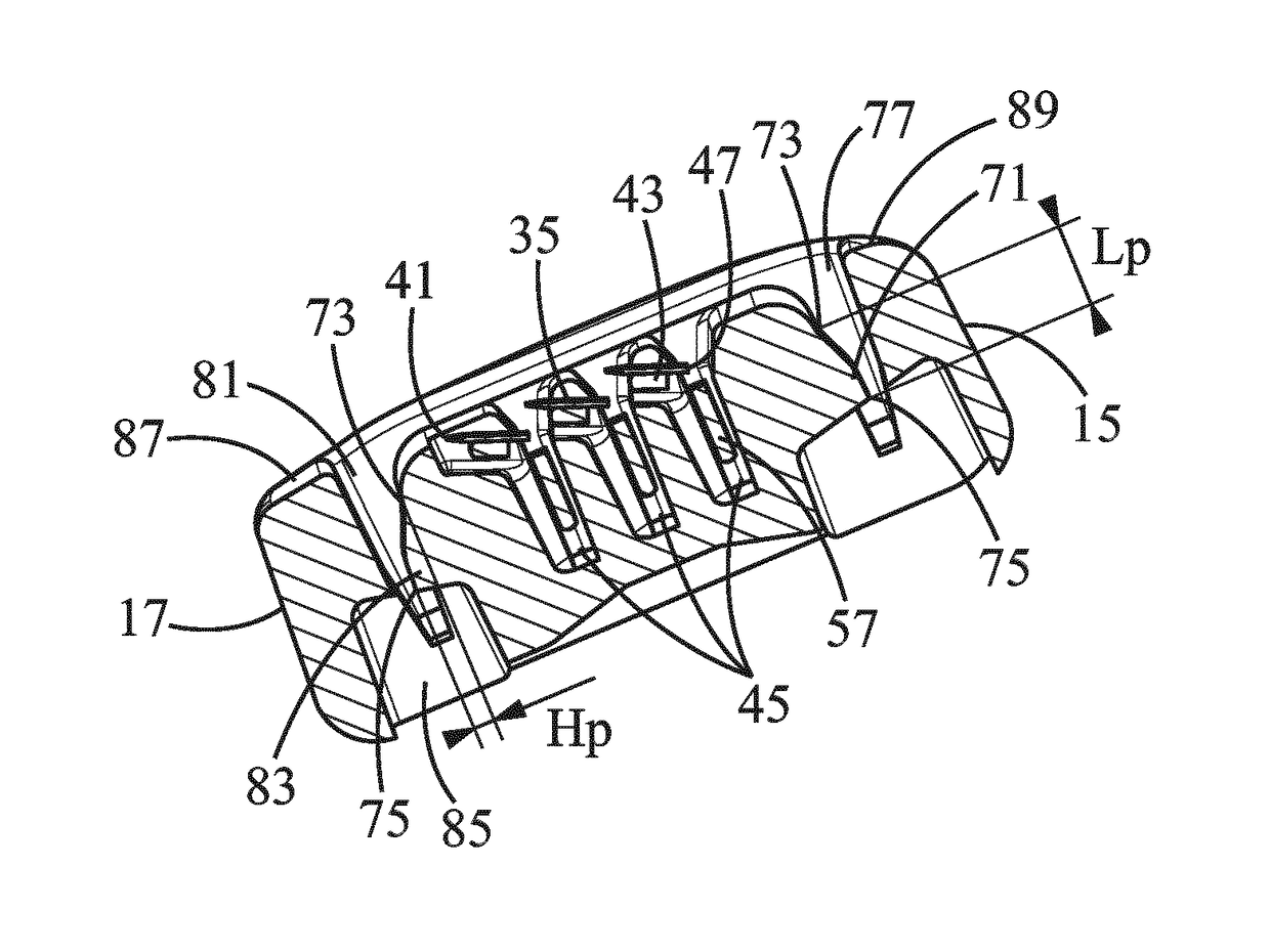
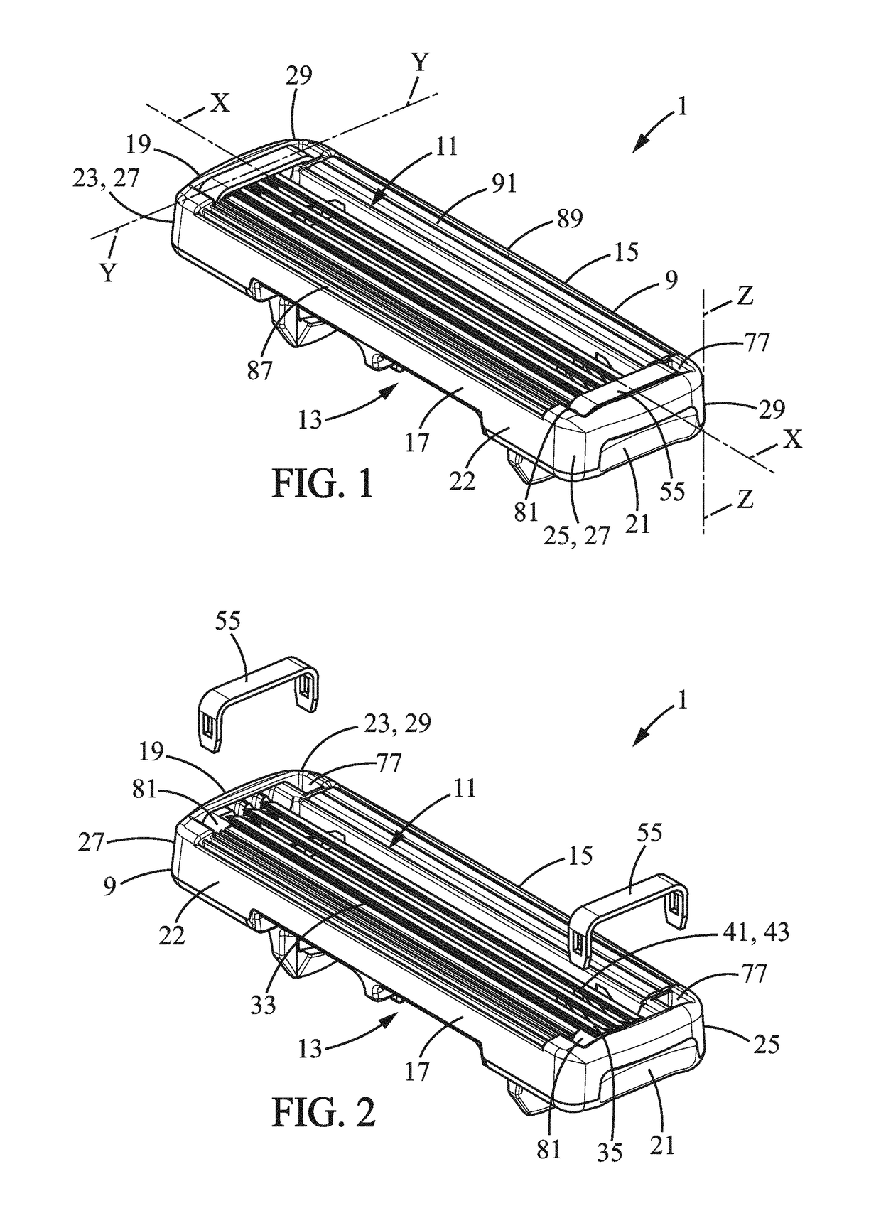
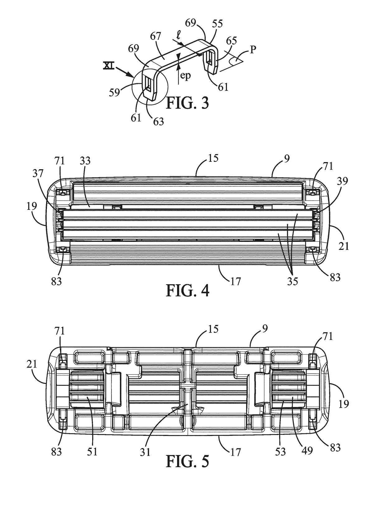
[0086]In the present invention, represented in FIGS. 1, 2, 4, 5, 6 and 7, the housing 9 has two cavities 77, 81, for example a first cavity 77 and a second cavity 81. Each of the cavities 77, 81 includes a protrusion 71. The first cavity 77 may be located at one side of the blade toward the first longitudinal side 15, and the second cavity 81 is located on the other side of the blade, toward the second longitudinal side 17.

[0087]In the first embodiment of the present invention, represented in FIGS. 1, 2, 4, 5, 6 and 7, the first leg 59 of the clip 55 is inserted in the first cavity 77 and the second leg 65 of the clip 55 is inserted in the second cavity 81.

second embodiment

[0088]In the present invention, as represented in FIG. 8, the protrusion 71 may be located on one of the two longitudinal sides 15, 17. More precisely, the protrusion 71 may be located either on the first longitudinal side 15, or on the second longitudinal side 17. As represented in FIGS. 7 and 8, a first protrusion 71 is located on the first longitudinal side 15 whereas a second protrusion 83 is located in a cavity 77 which is toward the second longitudinal side 17. In this embodiment of the present invention, represented in FIG. 8, at least one leg of the clip extends outside the shaving blade cartridge. For example, a groove which includes the protrusion 71 may be provided on the second longitudinal side 17, in which one leg of the clip 55 extends. The thickness of the groove can then be the same as than the thickness “ep” of the clip 55. Thus, the leg of the clip 55 does not protrude outside of the housing 9 from the groove.

[0089]In an embodiment of the present invention, the ho...


PUM


Abstract

A shaving blade cartridge includes a housing extending along a longitudinal axis, having a top side, a bottom side opposite to the top side and two longitudinal sides. The two longitudinal sides extend longitudinally along the longitudinal axis between the top and bottom sides. The housing is provided with at least one protrusion. The shaving blade cartridge further includes a cutting blade mounted in the housing between the longitudinal sides, and having a cutting edge extending along the longitudinal axis, and a clip retaining the cutting blade in the housing and having at least one leg. The leg of the clip has a recess, and the recess cooperates with the protrusion of the housing.

Description

[0001]This application is a national stage application of International Application No. PCT / EP2013 / 075614, filed on Dec. 5, 2013, the entire content of which is incorporated herein by reference.FIELD OF THE INVENTION[0002]The embodiments of the present invention relate to shaving blade cartridges and shavers having such shaving blade cartridges.BACKGROUND OF THE INVENTION[0003]In particular, the embodiments of the present invention relate to a shaving blade cartridge that includes:[0004]a housing extending along a longitudinal axis, having a top side, a bottom side opposite to the top side and two longitudinal sides extending longitudinally along the longitudinal axis between the top and bottom sides, the housing being provided with at least one protrusion,[0005]a cutting blade mounted in the housing between the longitudinal sides, and having a cutting edge extending along the longitudinal axis, and[0006]a clip retaining the cutting blade in the housing and having at least one leg.[...

Claims


Application Information

Patent Timeline
Patent Type & Authority Patents(United States)
IPC IPC(8): B26B21/40
CPCB26B21/4012B26B21/4068B26B21/4037B26B21/14B26B21/22
Inventor EFTHIMIADIS, DIMITRIOSZAFIROPOULOS, PANAGIOTISBOZIKIS, IOANNISMOUSTAKAS, PANAGIOTIS
Owner BIC VIOLEX SA
Why Eureka
Try Eureka