AI technical title is built by Patsnap AI team. It summarizes the technical point description of the patent document.
a coaxial connector and shielding technology, applied in the direction of coupling device connection, two-part coupling device, electrical apparatus, etc., to achieve the effect of reducing insertion loss, reducing swr, and high return loss
Active Publication Date: 2016-09-13
HOLLAND ELECTRONICS
View PDF29 Cites 13 Cited by
Summary
Abstract
Description
Claims
Application Information
AI Technical Summary
This helps you quickly interpret patents by identifying the three key elements:
Problems solved by technology
Method used
Benefits of technology
Benefits of technology
[0031]Electromagnetic shields include waveguides and devices causing electric charges within a metallic shield to redistribute and thereby reduce the field's effects in a protected device interior. Further, connector interior spaces can be shielded from particular external electromagnetic radiation when suitable material(s) and connector / shield geometries are used. Notably, various embodiments shield against both of signal ingress and signal egress.
[0051]A purpose of some embodiments of the invention is to maximize the RF shielding or ingress at low frequency while providing a good impedance match of the connector interface during operation. The inventor found that the thickness of the end surface or shield disc can also be an important factor in some embodiments. For example, thicknesses in the range of 0.5 to 1.5 mm were found to be effective in blocking frequencies under 100 MHz.
Problems solved by technology
Shields incorporating a disconnect switch may isolate a conductor otherwise exposed to unwanted RF signals.
Method used
Image
Click on the blue label to locate the original text in one second.
Reading with bidirectional positioning of images and text.
Examples
Embodiment Construction
[0081]The disclosure provided herein describes examples of some embodiments of the invention. The designs, figures, and descriptions are non-limiting examples of the embodiments they disclose. For example, other embodiments of the disclosed device and / or method may or may not include the features described herein. Moreover, disclosed advantages and benefits may apply to only certain embodiments of the invention and should not be used to limit the disclosed invention.
[0082]Unless otherwise stated, as used herein the term “coupled” includes direct and indirect connections. As such, where first and second devices are coupled, intervening devices including active devices may be located therebetween.
[0083]FIGS. 5A-C show schematics of a waveguide and of a waveguide in a connector 500A-C and FIGS. 5D-E illustrate selected waveguide dimensions 500D-E.
[0084]FIG. 5A shows a first coaxial connector schematic 500A. A coaxial connector 501 includes a body 502 and a waveguide 504 having a centra...
PUM
Abstract
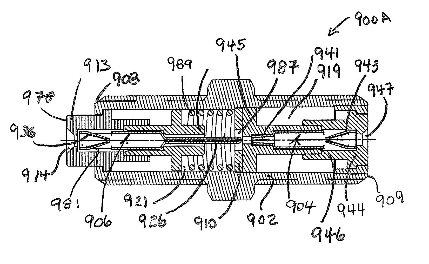
A shielded coaxial connector with a moveable center conductor and a stationary center conductor, the center conductors forming a disconnect switch that interoperates with a waveguide to shield one of the center conductors from radio frequency signals such as radio frequency signals carried by the other center conductor.
Description
PRIORITY CLAIM AND INCORPORATION BY REFERENCE[0001]This application is a continuation-in-part of U.S. patent application Ser. No. 14 / 494,488 filed Sep. 23, 2014.[0002]U.S. patent application Ser. No. 14 / 494,488 is a continuation-in-part of U.S. patent application Ser. No. 13 / 489,406 filed Jun. 5, 2012 (now U.S. Pat. No. 8,777,658 issued Jul. 15, 2014) and Ser. No. 13 / 723,800 filed Dec. 21, 2012 (now U.S. Pat. No. 9,048,600 issued Jun. 2, 2015), both of which claim the benefit of U.S. Prov. App. No. 61 / 612,922 filed Mar. 19, 2012.[0003]U.S. patent application Ser. No. 14 / 494,488 is a continuation-in-part of U.S. patent application Ser. No. 14 / 069,221 filed Oct. 31, 2013 which is a continuation-in-part of U.S. patent application Ser. No. 13 / 712,828 filed Dec. 12, 2012 which claims the benefit of U.S. Prov. Pat. App. No. 61 / 620,355 filed Apr. 4, 2012.[0004]U.S. patent application Ser. No. 14 / 949,488 claims the benefit of U.S. Prov. App. Nos. 61 / 969,204 filed Mar. 23, 2014 and 62 / 039,16...
Claims
Application Information
Patent Timeline
Application Date:The date an application was filed.
Publication Date:The date a patent or application was officially published.
First Publication Date:The earliest publication date of a patent with the same application number.
Issue Date:Publication date of the patent grant document.
PCT Entry Date:The Entry date of PCT National Phase.
Estimated Expiry Date:The statutory expiry date of a patent right according to the Patent Law, and it is the longest term of protection that the patent right can achieve without the termination of the patent right due to other reasons(Term extension factor has been taken into account ).
Invalid Date:Actual expiry date is based on effective date or publication date of legal transaction data of invalid patent.

