Shielded and multishielded coaxial connectors

a coaxial connector and shielding technology, applied in the direction of coupling device connection, two-part coupling device, electrical apparatus, etc., to achieve the effect of maximizing rf shielding, reducing rf cable ingress and/or egress, and reducing unwanted coaxial connector and/or coaxial connection rf transfer

Active Publication Date: 2015-08-18
HOLLAND ELECTRONICS
View PDF23 Cites 23 Cited by
  • Summary
  • Abstract
  • Description
  • Claims
  • Application Information

AI Technical Summary

Benefits of technology

[0027]Electromagnetic shields include waveguides and devices causing electric charges within a metallic shield to redistribute and thereby reduce the field's effects in a protected device interior. Further, connector interior spaces can be shielded from particular external electromagnetic radiation when suitable material(s) and connector / shield geometries are used. Notably, various embodiments shield against both of signal ingress and signal egress.
[0046]A purpose of some embodiments of the invention is to maximize the RF shielding or ingress at low frequency while providing a good impedance match of the connector interface during operation. The inventor found that the thickness of the end surface or shield disc can also be an important factor in some embodiments. For example, thicknesses in the range of 0.5 to 1.5 mm were found to be effective in blocking frequencies under 100 MHz.

Problems solved by technology

Shields incorporating a disconnect switch may isolate a conductor otherwise exposed to unwanted RF signals.

Method used


Image

  • Shielded and multishielded coaxial connectors
  • Shielded and multishielded coaxial connectors
  • Shielded and multishielded coaxial connectors

Examples


Embodiment Construction

[0075]The disclosure provided herein describes examples of some embodiments of the invention. The designs, figures, and descriptions are non-limiting examples of the embodiments they disclose. For example, other embodiments of the disclosed device and / or method may or may not include the features described herein. Moreover, disclosed advantages and benefits may apply to only certain embodiments of the invention and should not be used to limit the disclosed invention.

[0076]Unless otherwise stated, as used herein the term “coupled” includes direct and indirect connections. As such, where first and second devices are coupled, intervening devices including active devices may be located therebetween.

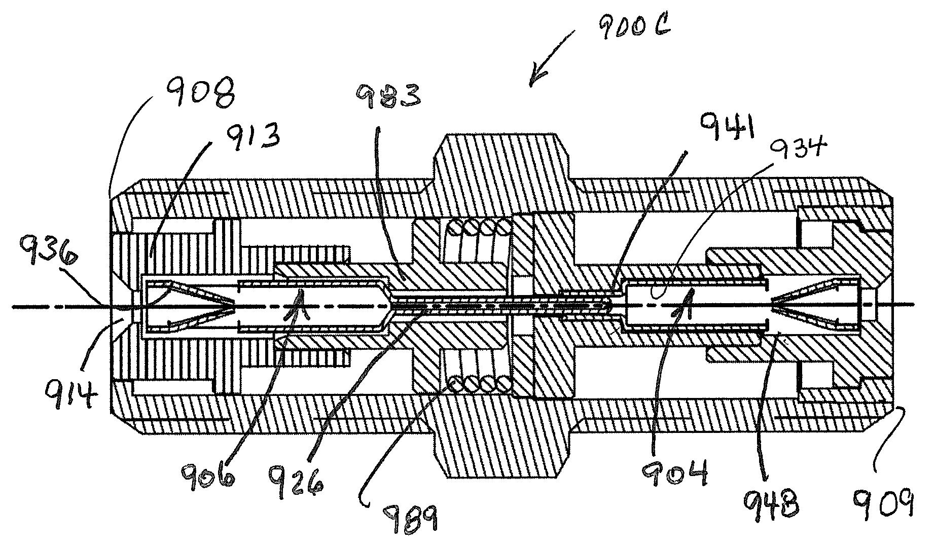
[0077]FIGS. 5A-C show schematics of a waveguide and of a waveguide in a connector 500A-C and FIGS. 5D-E illustrate selected waveguide dimensions 500D-E.

[0078]FIG. 5A shows a first coaxial connector schematic 500A. A coaxial connector 501 includes a body 502 and a waveguide 504 having a centra...


PUM


Abstract

A shielded coaxial connector with a moveable center conductor and a stationary center conductor, the center conductors forming a disconnect switch that interoperates with a waveguide to shield one of the center conductors from radio frequency signals such as radio frequency signals carried by the other center conductor.

Description

PRIORITY CLAIM AND INCORPORATION BY REFERENCE[0001]This application is a continuation-in-part of U.S. patent application Ser. No. 13 / 489,406 filed Jun. 5, 2012 (now U.S. Pat. No. 8,777,658 issued Jul. 15, 2014) and Ser. No. 13 / 723,800 filed Dec. 21, 2012, both of which claim the benefit of U.S. Prov. App. No. 61 / 612,922 filed Mar. 19, 2012. This application is a continuation-in-part of U.S. patent application Ser. No. 14 / 069,221 filed Oct. 31, 2013 which is a continuation-in-part of U.S. patent application Ser. No. 13 / 712,828 filed Dec. 12, 2012 which claims the benefit of U.S. Prov. Pat. App. No. 61 / 620,355 filed Apr. 4, 2012. This application claims the benefit of U.S. Prov. App. No. 61 / 969,204 filed Mar. 23, 2014 and 62 / 039,169 filed Aug. 19, 2014. All of the aforementioned applications are incorporated by reference herein, in their entireties and for all purposes.BACKGROUND OF THE INVENTION[0002]1. Field of the Invention[0003]The invention relates to the field of manufactured ra...

Claims


Application Information

Patent Timeline
Patent Type & Authority Patents(United States)
IPC IPC(8): H01R9/05H01R4/48H01R24/46H01R24/52
CPCH01R24/46H01R4/48H01R24/525H01R24/54
Inventor GOEBEL, GEORGEGIBSON, REEDHOLLAND, MICHAEL
Owner HOLLAND ELECTRONICS
Why Eureka
Try Eureka