Bearing structure

a technology of bearings and gas turbine engines, applied in the direction of elastic bearings, rigid support of bearing units, machines/engines, etc., can solve the problems of high and uncertain thrust loads urging the compressor upstream and the turbine downstream, high thrust loads, and high thrust loads. high and other problems

Active Publication Date: 2016-09-20
ROLLS ROYCE PLC
View PDF18 Cites 18 Cited by
  • Summary
  • Abstract
  • Description
  • Claims
  • Application Information

AI Technical Summary

Benefits of technology

[0014]By providing a first outer race that is axially slidable relative to the second outer race upon an increase in pressure in the pressure chamber defined by the first outer race, first compliant element and rigid diaphragm, it is possible to vary the axial spacing between the outer races and to induce an additional axial load on the bearings. When the pressure in the pressure chamber increases, the first compliant element is forced in one direction with the rigid diaphragm being forced in the opposing direction. As the rigid diaphragm is fixedly connected to the first outer race, the outer race is moved with the rigid diaphragm. The additional axial load can be induced in situations where under-loading of a bearing is predicted or measured to ensure that vibration / skidding of the bearing is avoided. Furthermore, by increasing the axial load on the potentially under-loaded bearing, this bearing becomes better able to transmit the thrust load thus resulting in a more equal sharing of the thrust load between the bearings.
[0031]The pressure inlet(s) may be duplicated for the / each pressure chamber so that the effects of any blocking or failure of the inlet(s) can be minimised.

Problems solved by technology

Thrust loads arise in a gas turbine engine as the result of pressure imbalances.
The thrust loads urging the compressor upstream and the turbine downstream are high and uncertain.
The thrust loads are often at theft maximum during the periods of highest power output for the engine.
Since single thrust bearings inevitably have a limited thrust capability, two or more bearings may be arranged adjacent one another to share the thrust load.
In these bearing arrangements, under-loading of one set of rolling elements may result in “skidding” of that set, which may cause damage, debris release and bearing failure.

Method used


Image

  • Bearing structure
  • Bearing structure
  • Bearing structure

Examples


first embodiment

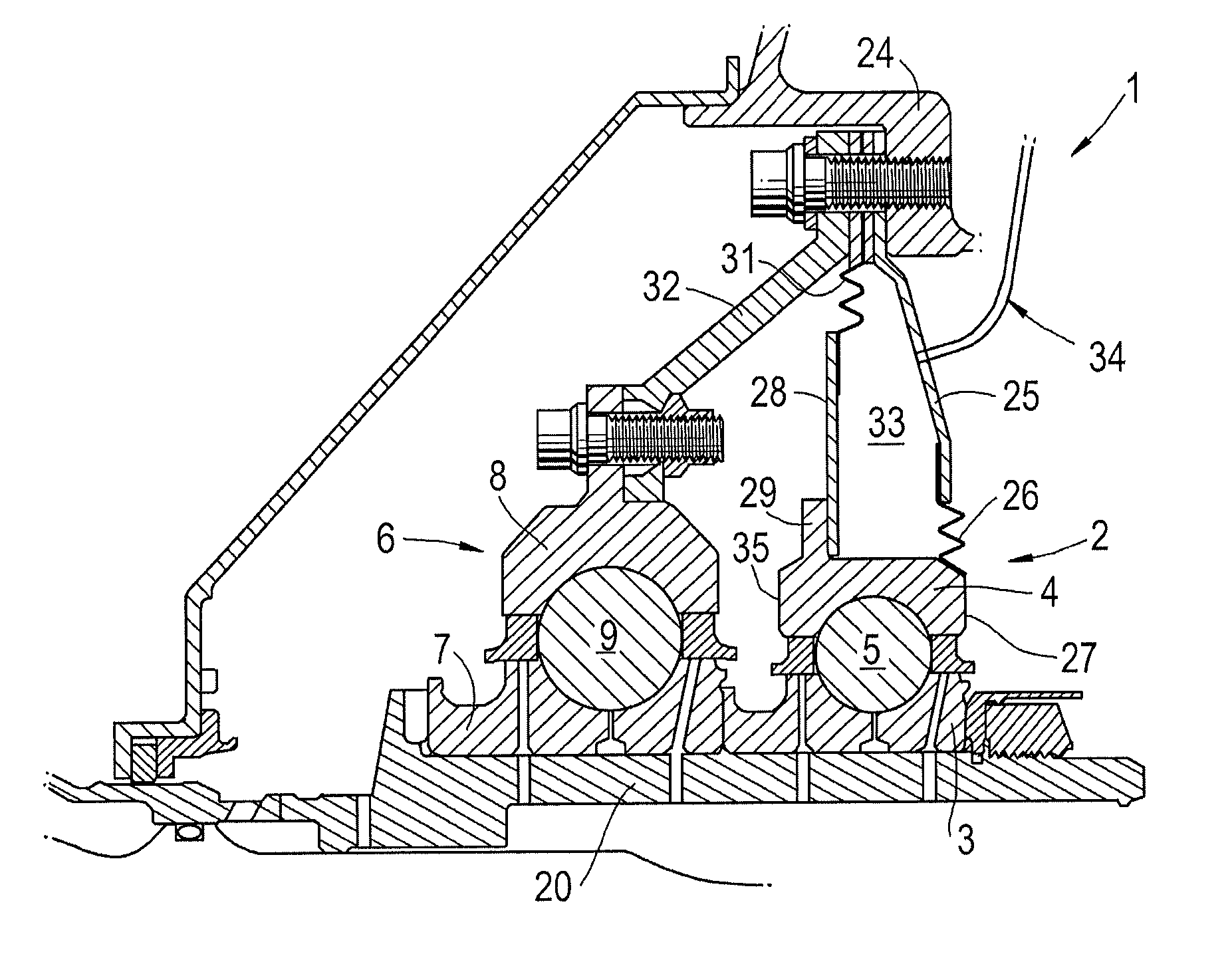
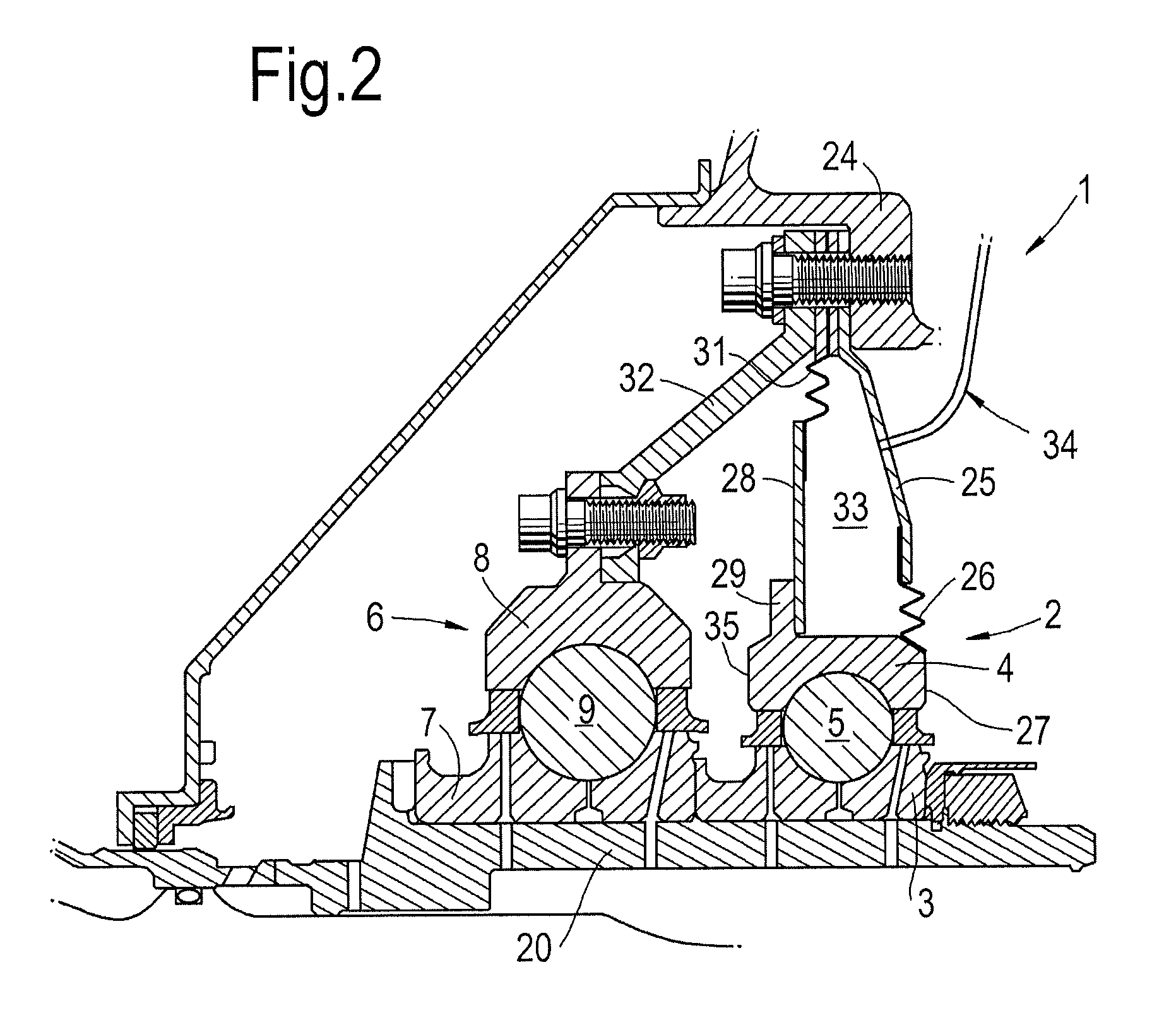
[0056]FIG. 2 shows a bearing structure 1 comprising a first bearing 2 having a first inner race 3, a first outer race 4 and a first set of rolling elements 5 housed between the first inner race 3 and the first outer race 4.

[0057]A second bearing 6 having a second inner race 7, a second outer race 8 and a second set of rolling elements 9 housed between the second inner race 7 and the second outer race 8 is provided adjacent the first bearing 2.

[0058]Both of the inner races 3, 7 are connected to and rotate with a rotor, in this case the LP rotor 20. The first outer race 4 faces an annular housing 24 which is a static component within the gas turbine engine. The annular housing has a support 32 which extends radially and axially. The second outer race 8 is fixedly connected to the support 32.

[0059]The housing 24 further comprises a first rigid radially extending casing 25.

[0060]A first compliant element 26 comprising flexible bellows is fixedly connected at its radially inner end to a ...

second embodiment

[0076]FIG. 4 shows the second embodiment mounted on the LP rotor 20. In this case, the second pressure chamber 38 is pressurised when the thrust load is high to reduce the maximum load on the second bearing 6. When the thrust load is low, (typically below 1000 lbf) the second pressure chamber 38 is vented and the first pressure chamber is pressurised so that the load on the second bearing 6 is increased.

[0077]In situations where thrust load is reversed (and therefore passes through zero), it is possible to rapidly reverse the pressurisation of the two chambers 33, 38 to control the bearing loadings and avoid skidding of under-loaded bearings. For example, if the first pressure chamber 33 is at a higher pressure than the second pressure chamber 38 in order to increase thrust load when the rotor thrust is low, at a pre-determined minimum load condition where the reverse rotor thrust is being off-set by a larger first bearing lead, the first pressure chamber 33 can vented whilst the se...


PUM


Abstract

Bearing structure including a first bearing, surrounded by a housing, having a first inner and outer race and first set of rolling elements between the inner and outer races and a second bearing having a second inner and outer race and second set of rolling elements between the second inner and outer races. A first compliant element is connected to the first outer race. A rigid diaphragm is connected to the first outer race between the compliant element and outer race, and is connected to the housing at its outer end. The first compliant element, outer race and rigid diaphragm at least partly define a pressure chamber. The first outer race is axially slidable relative to the second such that a pressure increase in the chamber changes the axial spacing between the first and second outer races, inducing additional axial load on the bearings which helps balance thrust load sharing.

Description

TECHNOLOGICAL FIELD[0001]The present disclosure relates to a bearing arrangement and a gas turbine engine having such a bearing arrangement.BACKGROUND[0002]In gas turbine engines, one or more rotors of the engine can be subjected to axial thrust loads during operation. Thrust loads arise in a gas turbine engine as the result of pressure imbalances. For example, a compressor has a higher downstream pressure than upstream pressure which forces the compressor upstream (towards the intake) whereas a turbine has a higher upstream pressure than downstream pressure which forces the turbine downstream (towards the exhaust nozzle). The thrust loads urging the compressor upstream and the turbine downstream are high and uncertain.[0003]The thrust loads are often at theft maximum during the periods of highest power output for the engine. In a gas turbine engine providing jet propulsion for an aircraft, this period of maximized power output can occur when the aircraft is taking-off and / or climbi...

Claims


Application Information

Patent Timeline
Patent Type & Authority Patents(United States)
IPC IPC(8): F16C27/00F01D25/16F16C35/04F16C19/06F16C19/52F16C19/54F16C33/78
CPCF16C19/54F01D25/16F16C19/06F16C19/522F16C33/7816F16C35/042F05D2220/32F05D2240/54F16C41/02F16C19/16F02C7/06F16C25/08F01D25/164F05D2260/15F16C2360/23F16C19/542
Inventor GALLIMORE, STEPHENFLETCHER, PAUL
Owner ROLLS ROYCE PLC
Why Eureka
Try Eureka