
Optical information recording medium and optical information recording medium reproducing device

a technology of optical information and recording medium, which is applied in the field of optical information recording medium and optical information recording medium reproducing device, can solve the problems of reducing the recording capacity of the optical disk, affecting the recording of user data, and affecting the recording of land track address,

Active Publication Date: 2016-11-01
SONY CORP
View PDF10 Cites 0 Cited by
  • Summary
  • Abstract
  • Description
  • Claims
  • Application Information

AI Technical Summary

Benefits of technology

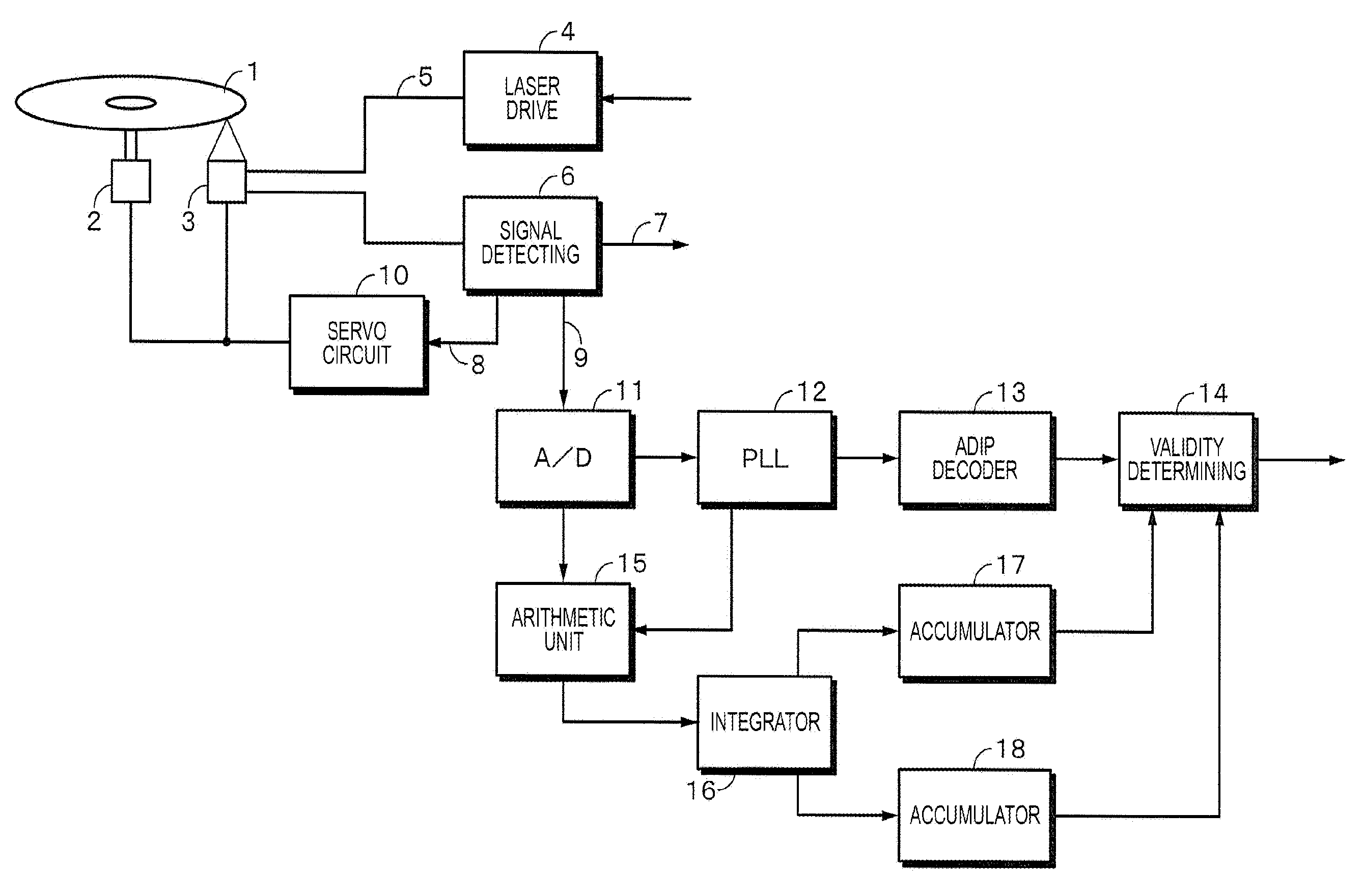
[0024]According to the present disclosure, when the recording is performed for both the groove and the land, the address of the land can be recorded only by the modulation of the groove. One of two pieces of information reproduced when scanning the land is considered to be a valid land address. A signal for determining the validity is added, and the valid land address information can be obtained in addition to the result of an error correction code.

Problems solved by technology

In recording the preformat pit, there is a problem that a recording area of user data and a recording capacity of the optical disk decrease.
However, it is difficult to record the address for the land track by the wobble.
Therefore, the phases of the wobbles are not aligned, and it is difficult to reproduce the wobbles normally.

Method used


Image

  • Optical information recording medium and optical information recording medium reproducing device
  • Optical information recording medium and optical information recording medium reproducing device
  • Optical information recording medium and optical information recording medium reproducing device

Examples


first embodiment

2. First Embodiment

[Main Difference from BD Format]

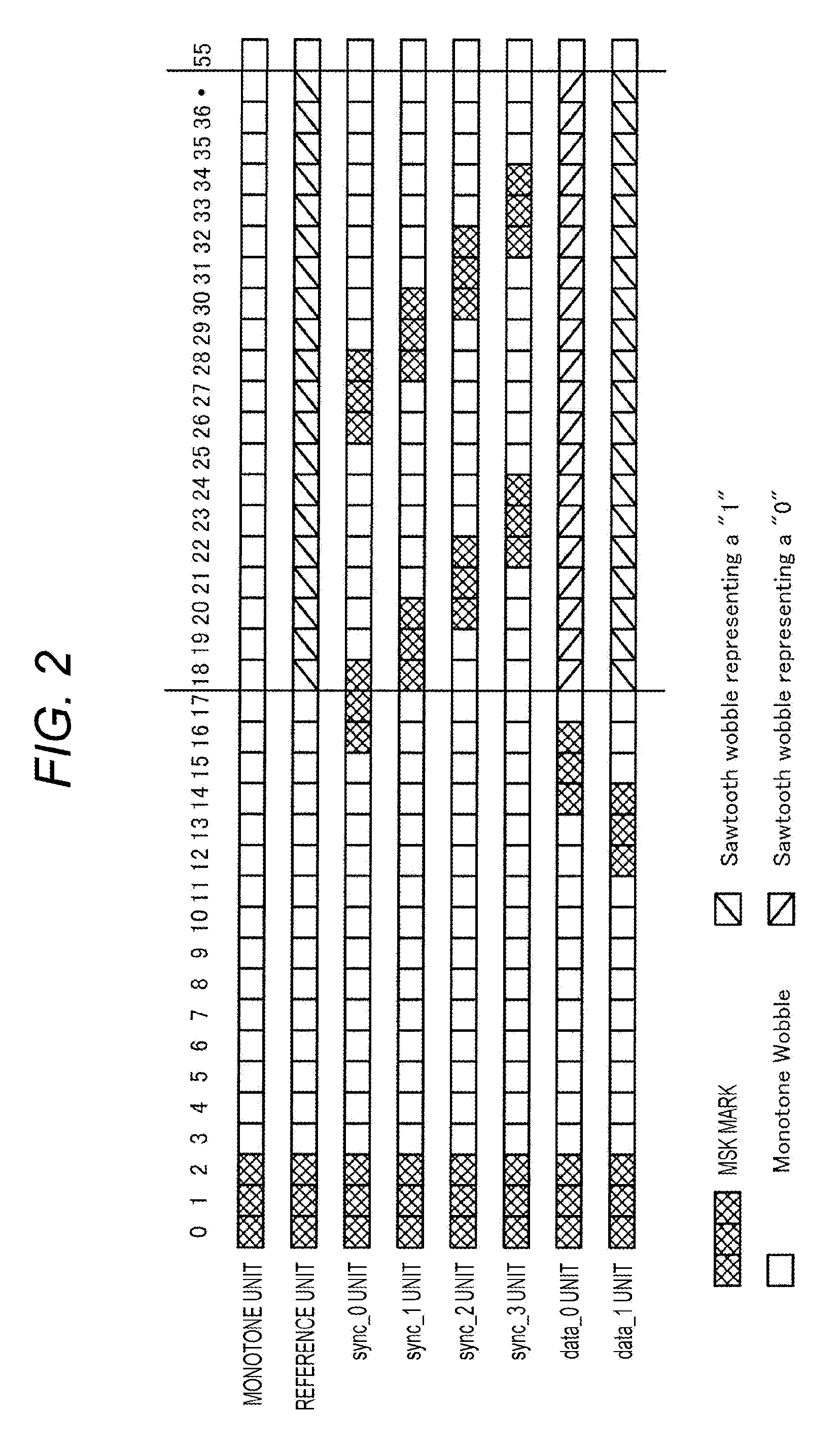
[0061]In a first embodiment of the present disclosure, the main difference from the BD format described above is as described below.[0062]In the BD format, a disk is rotated at a constant linear velocity (hereinafter refer to as CLV). On the other hand, in the present disclosure, the disk is rotated at a constant angular velocity (hereinafter referred to as CAV). A zone CAV can also be employed. The zone CAV divides the disk in a radial direction, forms a plurality of zones, and controls the CAV within the zone. In a spiral wobble track, phases of the basic wave of a wobble can be synchronized with each other in the radial direction of the disk by the CAV or the zone CAV.[0063]In the BD format, a groove recording format which records in a groove is used. On the other hand, in the present disclosure, recording is performed on both the groove and a land in order to increase a recording capacity. As described above, a trench is referre...

second embodiment

3. Second Embodiment

[Configuration of ADIP Unit]

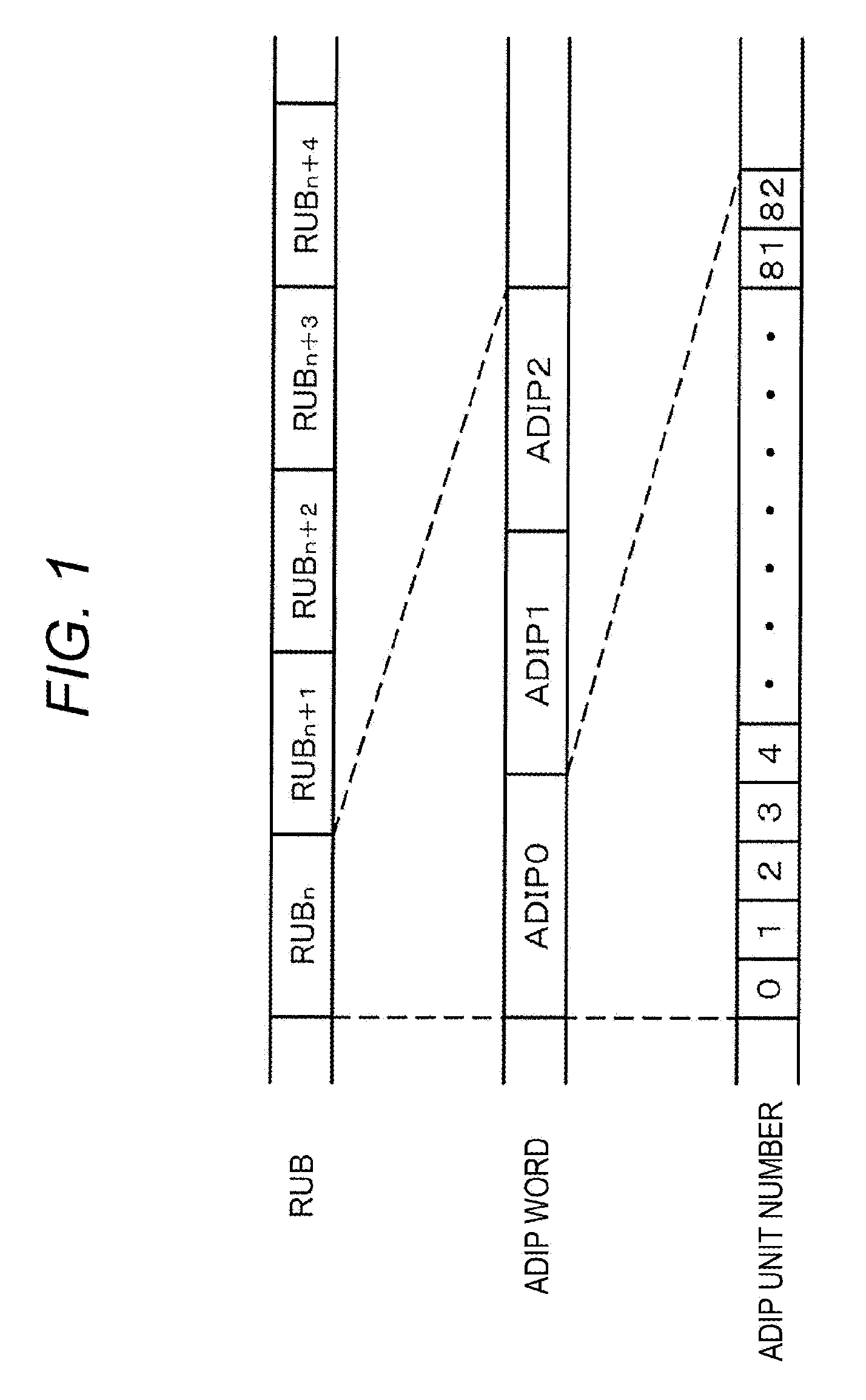
[0074]In the first embodiment described above, when a land track, for example the land track Trk(n+1) is scanned with a beam spot, an address of the land track can be acquired in the ADIP1 section. Then, the next ADIP2 section is identified as error data by error correction since the different address information is also reproduced. When the next land track Trk(n+3) is scanned with the beam spot, the address of the land track can be acquired in the ADIP2 section. Then, the previous ADIP1 section is identified as error data.

[0075]However, due to the reason such as detrack, the error correction is performed on the address of one adjacent groove track in an invalid address part, and the address may be treated as a valid address. In this case, two addresses are considered to be valid, and therefore, it is not possible to determine which address is valid. In a second embodiment of the present disclosure, such a problem is solved.

[0076]In th...


PUM

PropertyMeasurementUnit
constant angular velocityaaaaaaaaaa
polaritiesaaaaaaaaaa
areaaaaaaaaaaa

Abstract

Provided is a CAV or a zone CAV. A groove which continuously wobbles is preliminary formed and information is recorded in the groove and a land adjacent to the groove, the groove has a first wobble part which is modulated by groove address information, a second wobble part which is modulated by address information of one adjacent land, and a third wobble part which is modulated by address information of the other adjacent land, a first section sandwiched between the second wobble parts of adjacent two grooves and a second section sandwiched between the third wobble parts of the adjacent two grooves are formed on the land, and one of phases of wobbles on both sides of the first section and phases of wobbles on both sides of the second section are substantially in-phase.

Description

TECHNICAL FIELD[0001]The present disclosure relates to an optical information recording medium and an optical information recording medium reproducing device applied to, for example, a recordable optical disk.BACKGROUND ART[0002]Conventionally, an optical disk which records information or reproduces recorded information using laser light has been practically used. As types of the optical disk, there are a reproduction-only type, a write-once type, and a rewritable type. In the write-once type and the rewritable type, it is necessary that the address information indicating the position of the optical disk be preliminarily recorded for the recording of the information.[0003]As methods to record the address information, two types have been known. One is a format which records the address information as a preformat pit. The other is a format in which a signal that forms a trench referred to as a wobble for the trench is modulated by the address information. In recording the preformat pi...

Claims


Application Information

Patent Timeline
Patent Type & Authority Patents(United States)
IPC IPC(8): G11B7/007G11B7/24082G11B27/24G11B20/12
CPCG11B7/0079G11B7/24082G11B27/24G11B7/00718G11B2007/00754G11B2020/1265G11B2020/1268G11B2020/1278G11B2020/1287G11B2220/2541
Inventor SUZUKI, YUUICHIHORIGOME, JUNICHI
Owner SONY CORP
Learn More