Tire valve and molding seal for a tire valve

a technology of tire valves and molding seals, which is applied in the field of tire valves, can solve the problems of reduced production efficiency of union nut securing valves, reduced production efficiency of tyre parts, so as to achieve favourable tolerance and surface properties of seals, increase manufacturing tolerances, and reduce production costs

Active Publication Date: 2016-11-15
WEGMANN AUTOMOTIVE GMBH
View PDF39 Cites 0 Cited by
  • Summary
  • Abstract
  • Description
  • Claims
  • Application Information

AI Technical Summary

Benefits of technology

[0011]As a result of the present invention, favourable tolerance and surface properties of the seal are combined with high tightening and release moments for securing the union nut, so that in particular also areas of application with greater manufacturing tolerances are developed for the present invention.

Problems solved by technology

However, both solutions, considered in each case in themselves, are disadvantageous technically: A shoulder or flat seal typically consisting of a flat rubber ring and optionally provided with a shoulder section, places relatively small demands on the evenness of the support surface (that is, the outer-lying flat edge section of the rim bore) and on the aperture tolerances of this rim bore, since the large rubber volume of such seals compensates deviations in simple manner.
However, it is disadvantageous that during installation of valves using such seals, (low) torque limits may not be exceeded, this would lead to the destruction of the seal.
Since in addition the sealing elements are deformed under pressure, very low release moments for the union nut securing the valve are usually produced in disadvantageous manner.
On the other hand, it is disadvantageous that such an O-ring seal places very high requirements on the evenness of the support surface in the rim bore edge region and the bore tolerances themselves, so that here in some cases considerable additional expense is necessary for manufacture and assembly.

Method used


Image

  • Tire valve and molding seal for a tire valve
  • Tire valve and molding seal for a tire valve

Examples


Embodiment Construction

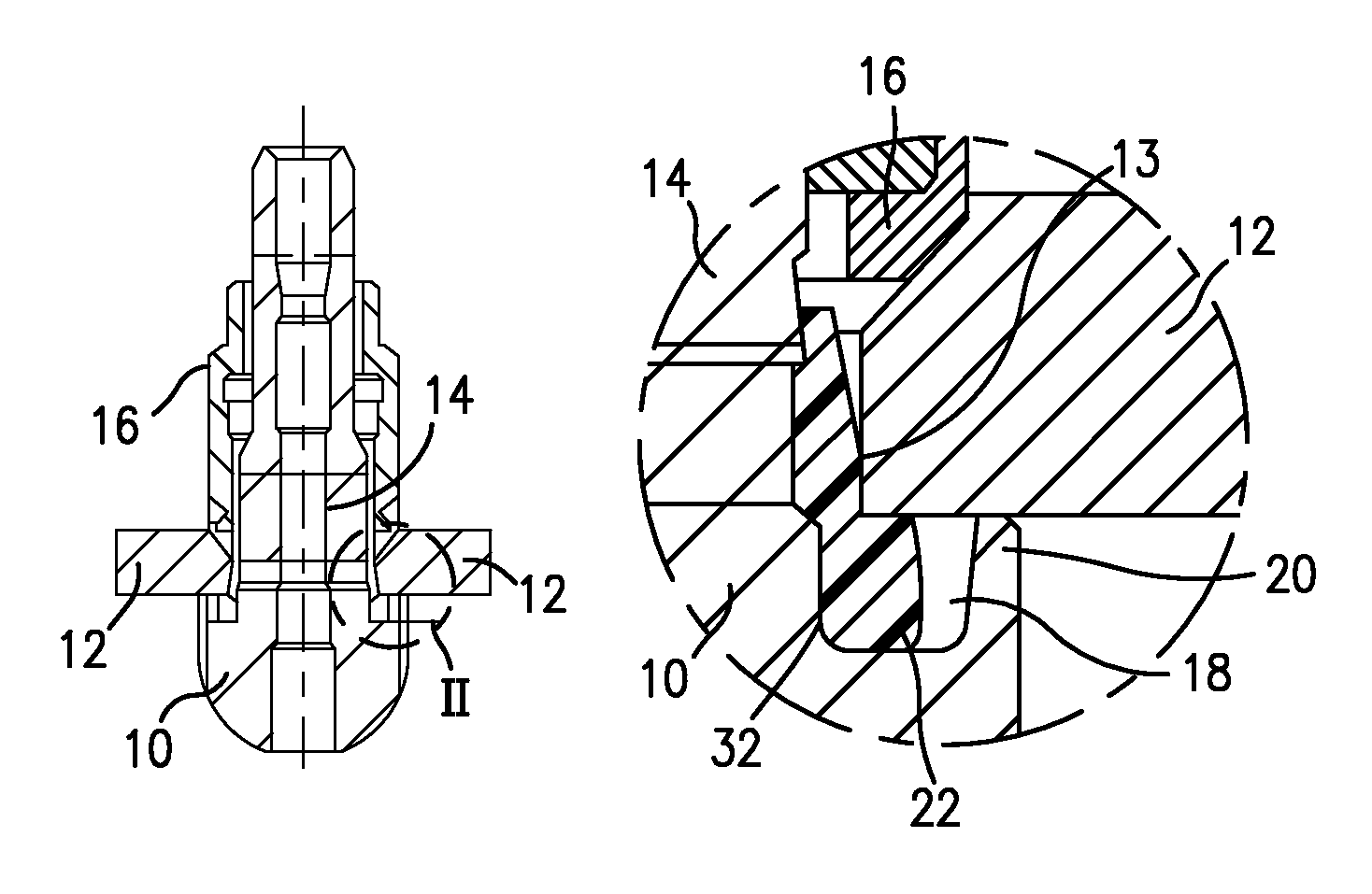
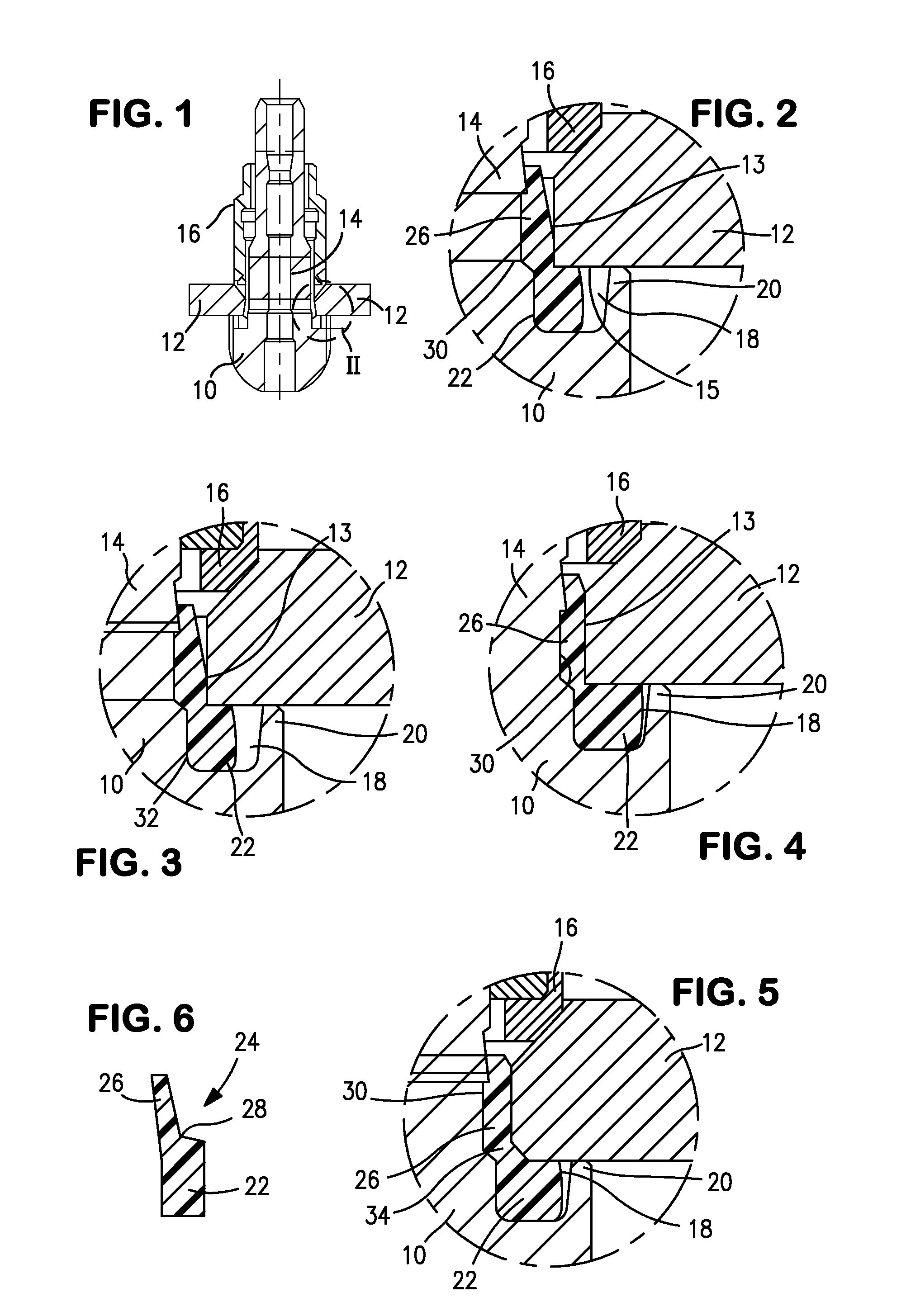
[0019]FIG. 1 shows in the schematic sectional view, the tire valve of the invention as air tire valve according to a first, preferred embodiment of the present invention. More precisely, a lower valve body 10 sits in a rim interior of a vehicle rim 12 (the valve or rim bore region of this rim is shown by the reference number 12), and an upper valve body section 14 having an annular shallow groove 30 extends through the rim bore thus described and offers in otherwise known manner, the possibility for accessing the valve. A union nut 16, which, see in particular the detailed drawings of the cutout II in FIG. 1, engages on a cross-sectionally bevelled (chamfered) region of the valve bore in gripped state (that is, assembly state), is placed on an outer thread of the upper valve body section 14.

[0020]The lower valve body section 10 has in the contact region with the valve or rim bore region 12 (which has an annular end face 13 and an under surface in the form of a flat edge 15), an annu...


PUM


Abstract

A tire valve having a valve body engaging in a rim bore of a rim, in particular vehicle rim, which valve body forms a lower valve body section arranged on a side of the rim, in particular in the rim interior, in the assembled state, and an upper valve body section projecting from the rim bore, and in the region of the upper valve body section is designed to cooperate with a union nut, wherein the lower valve body section forms a ring shoulder offering an abutment for a flat edge section of the rim bore, and in which a ring groove which is open to the edge section is molded, and against which the edge section can be gripped by tightening the union nut, and a molded seal made from resilient material is provided to seal the rim bore with respect to the valve body, so that in the assembled and gripped state, an annular chamber section of the molded seal engages in the ring groove and rests in sealing manner on the edge section of the rim bore.

Description

BACKGROUND OF THE INVENTION[0001]The present invention relates to a tire valve, in particular gas and / or air tire valve, according to the preamble of the main claim, and a moulded seal which is suitable and provided in particular for use in such a valve.[0002]Various approaches are known from the state of the art for sealing against air loss between an air tire valve and the valve bore (below also: rim bore) surrounding the air tire valve in the air tire rim. Firstly, so-called shoulder or flat seals exist, secondly O-ring seals are used.[0003]However, both solutions, considered in each case in themselves, are disadvantageous technically: A shoulder or flat seal typically consisting of a flat rubber ring and optionally provided with a shoulder section, places relatively small demands on the evenness of the support surface (that is, the outer-lying flat edge section of the rim bore) and on the aperture tolerances of this rim bore, since the large rubber volume of such seals compensat...

Claims


Application Information

Patent Timeline
Patent Type & Authority Patents(United States)
IPC IPC(8): F16K15/20B60C29/02
CPCB60C29/02Y10T137/3584Y10T137/3786
Inventor PALAORO, RENATO
Owner WEGMANN AUTOMOTIVE GMBH
Why Eureka
Try Eureka