Closed-end blind rivet with a crimped shank and method of manufacture thereof

a closed-end, shank technology, applied in the field of blind rivets, can solve the problems of mandrel head fracture, difficult manufacturing, and insufficient resistance of grooves to prevent mandrel heads, and achieve the effects of convenient production, reduced manufacturing cost, and improved manufacturing tolerances

Inactive Publication Date: 2005-02-15
NEWFREY
View PDF5 Cites 33 Cited by
  • Summary
  • Abstract
  • Description
  • Claims
  • Application Information

AI Technical Summary

Benefits of technology

Accordingly, it is an object of the present invention to provide a blind rivet with a crimped shank and method of manufacture thereof which overcomes the disadvantages of the prior art and provides for greater manufacturing tolerances and ease of production.
It is another object of the invention to provide a blind rivet and method of manufacture thereof which is relatively inexpensive, simple to produce and reliable in use in that its failure rate is de minimus and the product produced is leakproof.

Problems solved by technology

This is particularly difficult when the rivet bodies are made of intractable material such as stainless steel, carbon steel or the like.
If the grooves are too deep the rivet body will crack and if they are too shallow, the grooves will not provide sufficient resistance to prevent the mandrel head from pulling into or even through the rivet body.
This can result in two problems.
Firstly, during setting in softer materials, the grooves are required to be deeper to prevent the mandrel head from pulling through the rivet body.
However, this can cause fracture of the body.
If the grooves are not at an optimum depth, the mandrel pulls through the body causing radial expansion of the rivet body between the grooves which can result in the splitting of the workpiece material if the expansion takes place within the bore formed in the workpiece, in which the rivet is located.
Secondly, if the grooves are less than optimum, during the setting of a rivet, the mandrel head can pull through the rivet body since there is insufficient resistance from the soft workpiece materials to help provide resistance to the head of the mandrel pulling into the rivet body.
This can result in part of the stem attached to the head of the mandrel protruding from the flange giving a potentially hazardous condition.

Method used


Image

  • Closed-end blind rivet with a crimped shank and method of manufacture thereof
  • Closed-end blind rivet with a crimped shank and method of manufacture thereof
  • Closed-end blind rivet with a crimped shank and method of manufacture thereof

Examples


Embodiment Construction

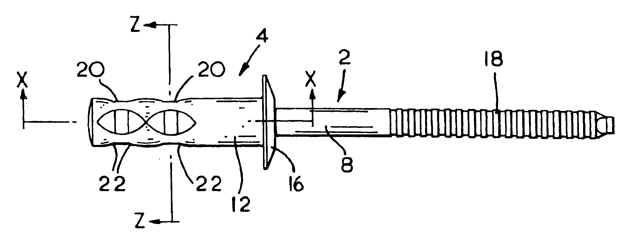
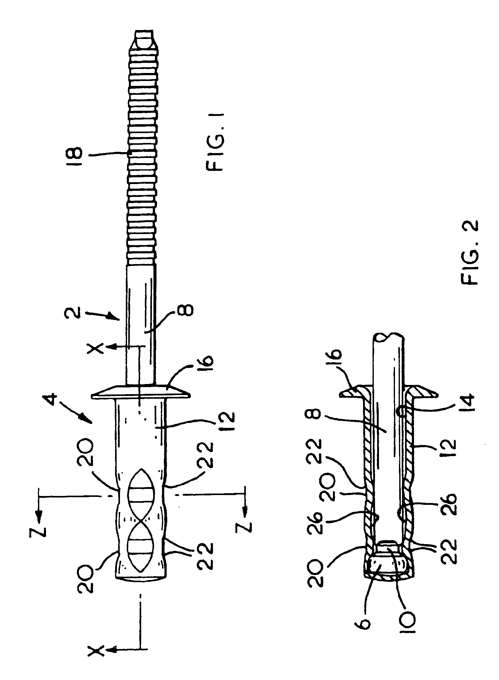
With reference to the accompanying drawings, FIG. 1 shows a blind rivet having a mandrel (2) and a rivet body (4). The mandrel (2) has a mandrel head (6) attached to one end of a stem (8). The stem (8) comprises a breakneck (10) located adjacent the mandrel head (6). The diameter of the stem (8) is substantially uniform along the length of the stem (8).

The rivet body (4) has a tubular shank (12) having a flange (16) formed at one end of the shank (12). A bore (14), shown in FIG. 2, extends through the flange (16) and through a substantial part of the length of the shank (12). The head (6) of the mandrel (2) is located within the shank (12), the outer diameter of the head (6) being larger than the bore (14). The stem (8) of the mandrel (2) extends from the head (6) through the bore (14) and extends from the body (4) of the rivet away from the flange (16). Ridges (18), shown only in FIG. 1, are formed on part of the exposed end of the stem (8) to assist the rivet setting tool in gripp...


PUM


Abstract

A blind rivet having a mandrel with a predetermined breakable stem disposed within a body with a bored shank. A radial flange is formed on one end of the shank to engage a workpiece and at the other end of the shank there is disposed within the shank an enlarged head of the stem the diameter of which is greater than the diameter of the bore of the shank. The breakneck of the stem formed with at least two series of radial impressions formed around the circumference of the shank at predetermined distances from the flange. Ribs are formed alternately between the radial impressions in the same horizontal series therewith.

Description

BACKGROUND OF THE INVENTIONThis invention relates to a blind rivet and, more particularly, to a closed-end blind rivet with a crimped shank and method of manufacture thereof.Blind rivets are well-known and generally comprise a mandrel having a pulling stem with a radially enlarged head attached at one end and a tubular shell having a generally cylindrical shaped shank having a radial flange formed at one end of the shank for engaging a face of the workpiece. An axial bore is formed through the flange and passes a substantial way into the shank. The radially enlarged head of the mandrel is located within the shank towards the end remote from the flange adjacent an end of the bore. The enlarged head has a circumference which is greater than that of the bore. The pulling stem extends from the enlarged head through the length of the bore and extends away from the body of the rivet. A breakneck is formed on part of the stem and which is located within the shank. When the rivet is set, th...

Claims


Application Information

Patent Timeline
Patent Type & Authority Patents(United States)
IPC IPC(8): F16B19/10F16B19/04
CPCF16B19/1054
Inventor JENNINGS, GARYPROBERT, PETER C.
Owner NEWFREY
Why Eureka
Try Eureka