
Methods and apparatus for improving signal quality in wearable biometric monitoring devices

a biometric monitoring and signal quality technology, applied in the field of monitoring devices and methods, can solve the problems of time-varying changes in photon intensity, motion artifacts, and difficult ascertaining of signals of interest, so as to facilitate signal quality estimation, improve biometric fit, and improve the effect of biometric fi

Active Publication Date: 2017-10-17
YUKKA MAGIC LLC
View PDF490 Cites 73 Cited by
  • Summary
  • Abstract
  • Description
  • Claims
  • Application Information

AI Technical Summary

Benefits of technology

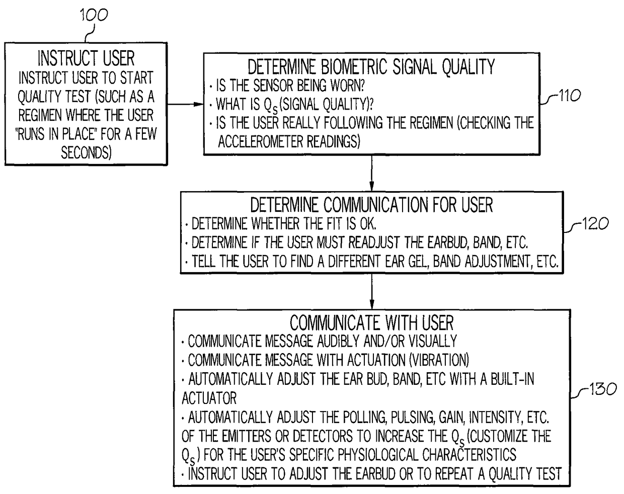
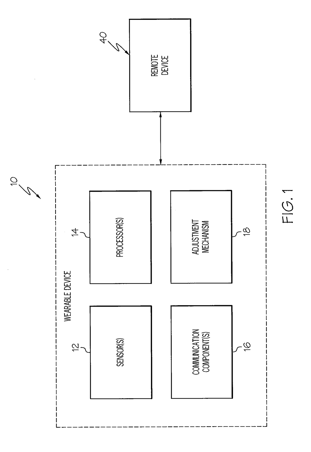
[0006]According to some embodiments of the present invention, a wearable biometric monitoring device is configured to assess the biometric signal quality of one or more sensors associated with the biometric monitoring device, determine how the user should adjust the device to improve the biometric fit, and instruct the user to wear the device a certain way (e.g., audio-visually via a remote device). In some embodiments, this may involve an iterative approach. In some embodiments, communicating instructions to a user may include instructing the user to execute a testing regimen while wearing the device. The testing regimen facilitates an estimation of signal quality that can be used to provide feedback to the user that he / she needs to adjust the device to improve the biometric fit (and hence the biometric signal quality).

Problems solved by technology

If the incidental and scattered photon count magnitude changes due to light coupling variation between the source or detector and the skin or other body tissue, then the signal of interest can be difficult to ascertain due to large photon count variability caused by motion artifacts.
Physical activity, such as walking, cycling, running, etc., may cause motion artifacts in the optical scatter signal from the body, and time-varying changes in photon intensity due to motion artifacts may swamp-out time-varying changes in photon intensity due to blood flow changes.
Environmental artifacts, such as ambient light noise, as well as motion-coupled ambient light noise can further swamp-out blood-flow related signals.
This can result in a much lower accuracy in metrics derived from PPG data, such as heart rate and breathing rate.
The signal quality from a biometric sensor, such as a PPG sensor, in a wearable monitoring device increases when the monitoring device is worn correctly and decreases when the monitoring device is worn incorrectly.
For example, a user may go for a run with a biometric earbud and expect accurate heart rate zone information from the sensor(s) therein, only to find the sensor data is erroneous due to a poor fitting of the biometric earbud within the ear.
Unfortunately, without some way to measure signal quality, a user may not know if sensor signal quality is adequate.

Method used


Image

  • Methods and apparatus for improving signal quality in wearable biometric monitoring devices
  • Methods and apparatus for improving signal quality in wearable biometric monitoring devices
  • Methods and apparatus for improving signal quality in wearable biometric monitoring devices

Examples


Embodiment Construction

[0040]The present invention will now be described more fully hereinafter with reference to the accompanying figures, in which embodiments of the invention are shown. This invention may, however, be embodied in many different forms and should not be construed as limited to the embodiments set forth herein. Like numbers refer to like elements throughout. In the figures, certain layers, components or features may be exaggerated for clarity, and broken lines illustrate optional features or operations unless specified otherwise. In addition, the sequence of operations (or steps) is not limited to the order presented in the figures and / or claims unless specifically indicated otherwise. Features described with respect to one figure or embodiment can be associated with another embodiment or figure although not specifically described or shown as such.

[0041]It will be understood that when a feature or element is referred to as being “on” another feature or element, it can be directly on the o...


PUM


Abstract

A wearable biometric monitoring device is configured to assess the biometric signal quality of one or more sensors associated with the monitoring device, determine how the user should adjust the device to improve the biometric fit, and instruct the user to wear the biometric monitoring device a certain way. Communicating instructions to a user may include instructing the user to execute a testing regimen while wearing the biometric monitoring device. The testing regimen facilitates an estimation of a signal quality that can be used to provide feedback to the user that he / she needs to adjust the device to improve the biometric fit and the biometric signal quality.

Description

RELATED APPLICATIONS[0001]This application claims the benefit of and priority to U.S. Provisional Patent Application No. 62 / 056,510 filed Sep. 27, 2014, and U.S. Provisional Patent Application No. 62 / 110,655 filed Feb. 2, 2015, the disclosures of which are incorporated herein by reference as if set forth in their entireties.FIELD OF THE INVENTION[0002]The present invention relates generally to monitoring devices and methods, more particularly, to monitoring devices and methods for measuring physiological information.BACKGROUND OF THE INVENTION[0003]Photoplethysmography (PPG) is based upon shining light into the human body and measuring how the scattered light intensity changes with each pulse of blood flow. The scattered light intensity will change in time with respect to changes in blood flow or blood opacity associated with heart beats, breaths, blood oxygen level (SpO2), and the like. Such a sensing methodology may require the magnitude of light energy reaching the volume of fles...

Claims


Application Information

Patent Timeline
Patent Type & Authority Patents(United States)
IPC IPC(8): G08B21/18A61B5/00H04Q9/00H04R1/10A61B5/11A61B5/024A61B5/1455
CPCH04Q9/00A61B5/6802G08B21/18H04R1/1091A61B5/02405A61B5/1118A61B5/14551A61B5/7221H04R1/1008H04R1/1016A61B5/6815
Inventor AUMER, MICHAEL EDWARDLEBOEUF, STEVEN FRANCIS
Owner YUKKA MAGIC LLC
Learn More