Variable geometry turbine

a turbine and variable geometry technology, applied in the direction of internal combustion piston engines, machines/engines, engine components, etc., can solve the problems of engine non-compliant with government exhaust emission regulations, exhaust gas temperature can often fall below the threshold temperature, system accumulation of undesirable accumulations,

Active Publication Date: 2017-11-14
CUMMINS LTD WEST YORKSHIRE
View PDF6 Cites 6 Cited by
  • Summary
  • Abstract
  • Description
  • Claims
  • Application Information

AI Technical Summary

Benefits of technology

[0022]It is one object of the present invention to obviate or mitigate at least one of the

Problems solved by technology

Operation of the exhaust gas after-treatment system below the threshold temperature range will cause the system to build up undesirable accumulations which must be burnt off in a regeneration cycle to allow the system to return to designed performance levels.
In addition, prolonged operation of the exhaust gas after-treatment system below the threshold temperature without regeneration will disable the system and cause the engine to become non-compliant with government exhaust emission regulations.
However, in some conditions, such as light load conditions and/or cold ambient temperature conditions, the exhaust gas temperature can often fall below the threshold temperature.
If the exhaust from an engine is restricted to too great an extent, this can lead to excessive heat generation in the engine cyli

Method used


Image

  • Variable geometry turbine
  • Variable geometry turbine
  • Variable geometry turbine

Examples


Embodiment Construction

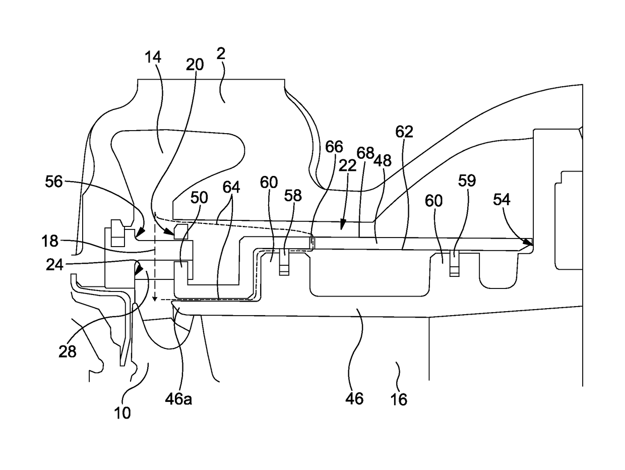
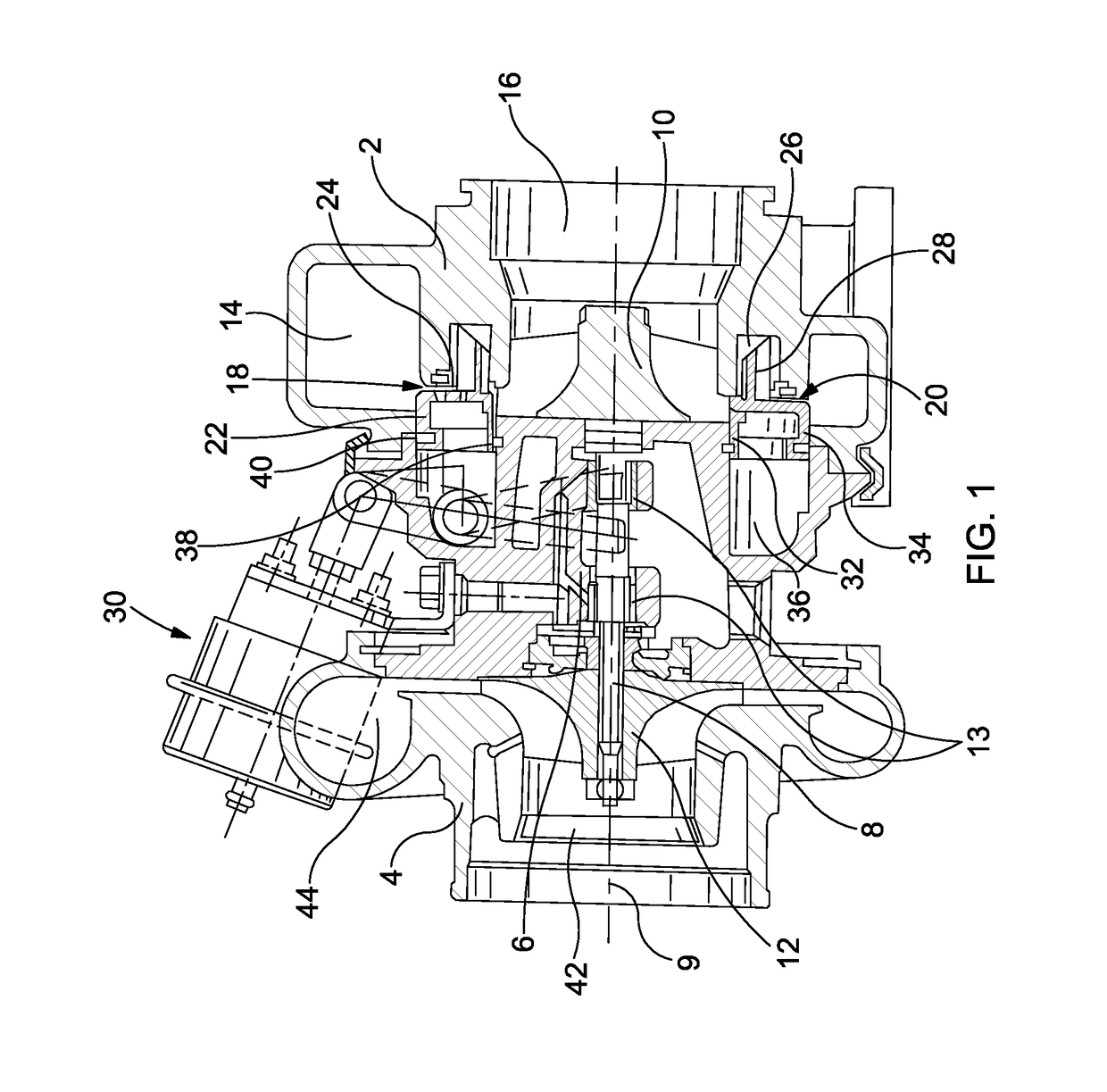
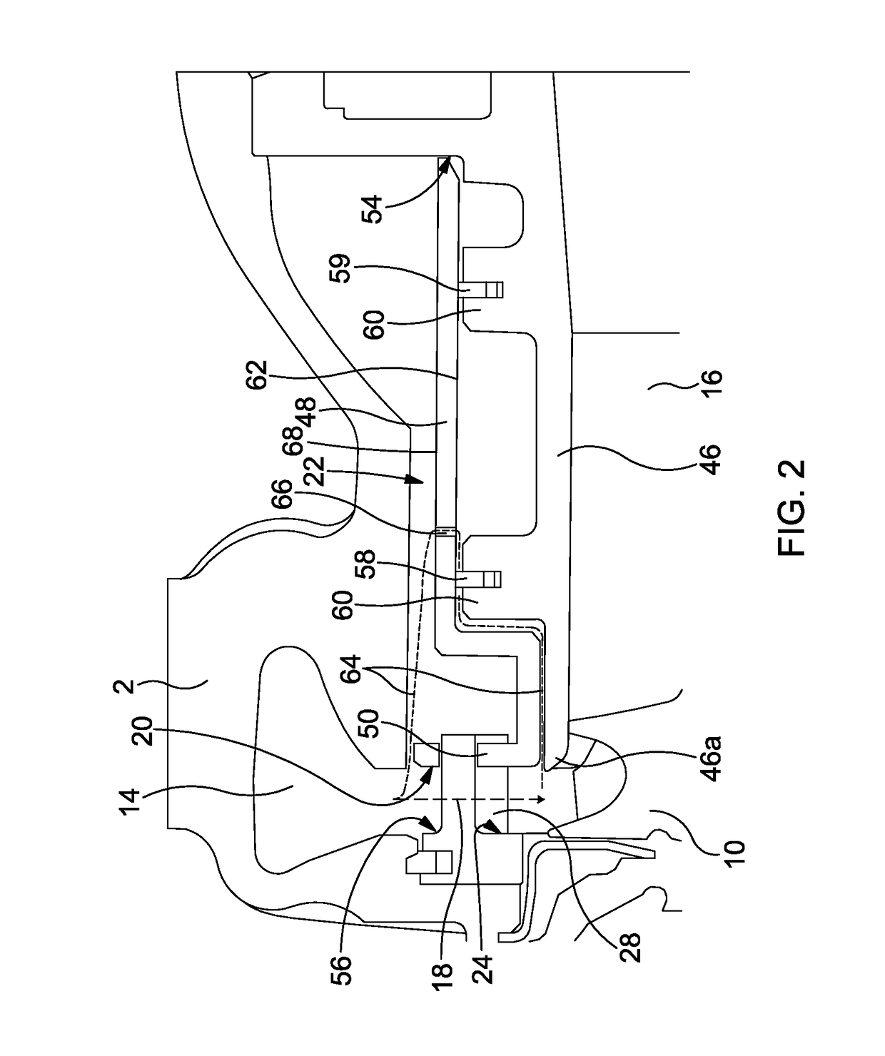
[0071]FIG. 1 illustrates a known variable geometry turbocharger comprising a turbine housing 2 and a compressor housing 4 interconnected by a central bearing housing 6. A turbocharger shaft 8 extends from the turbine housing 2 to the compressor housing 4 through the bearing housing 6. A (radial-inflow axial-outflow type) turbine wheel 10 is mounted on one end of the shaft 8 for rotation within the turbine housing 2, and a (axial-inflow radial-outflow type) compressor wheel 12 is mounted on the other end of the shaft 8 for rotation within the compressor housing 4. The shaft 8 rotates about turbocharger axis 9 on bearings 13 located in the bearing housing 6, and thereby acts as an axle for the turbine wheel 10 and the compressor wheel 12.

[0072]The turbine housing 2 defines an inlet volute 14 to which gas from an internal combustion engine (not shown) is delivered. The exhaust gas flows from the inlet volute 14 to an axial outlet passage 16 via an inlet passage 18 and the turbine wheel...


PUM


Abstract

A variable geometry turbine comprises a turbine wheel and a primary inlet passage of variable axial width. The turbine has a secondary inlet passage provides a flow path for a working fluid which circumnavigates at least part of the primary inlet passage. A seal element and one or more apertures are cooperable to selectively allow or prevent fluid flow through the secondary inlet passage. The ratio of the minimum cross-sectional area of the flow path through the primary inlet passage to that of the secondary inlet passage is between 1.3 and 1.7.

Description

BACKGROUND OF THE INVENTION[0001]1. Field of the Invention[0002]The present invention relates to a variable geometry turbine and has particular, but not exclusive, application to variable geometry turbochargers.[0003]2. Description of the Related Art[0004]Turbochargers are well known devices for supplying air to the intake of an internal combustion engine at pressures above atmospheric (boost pressures). A conventional turbocharger essentially comprises an exhaust gas driven turbine wheel mounted on a rotatable shaft within a turbine housing. Rotation of the turbine wheel rotates a compressor wheel mounted on the other end of the shaft within a compressor housing. The compressor wheel delivers compressed air to the engine intake manifold. The turbocharger shaft is conventionally supported by journal and thrust bearings, including appropriate lubricating systems, located within a central bearing housing connected between the turbine and compressor wheel housing.[0005]The turbine stag...

Claims


Application Information

Patent Timeline
IPC IPC(8): F02B37/22F01D17/14F01D17/16
CPCF02B37/22F01D17/167F01D17/141F01D17/143F02B37/24F05D2220/40Y02T10/12
Inventor LUCK, DAVID A.CARTER, JEFFREY
Owner CUMMINS LTD WEST YORKSHIRE
Why Eureka
Try Eureka