

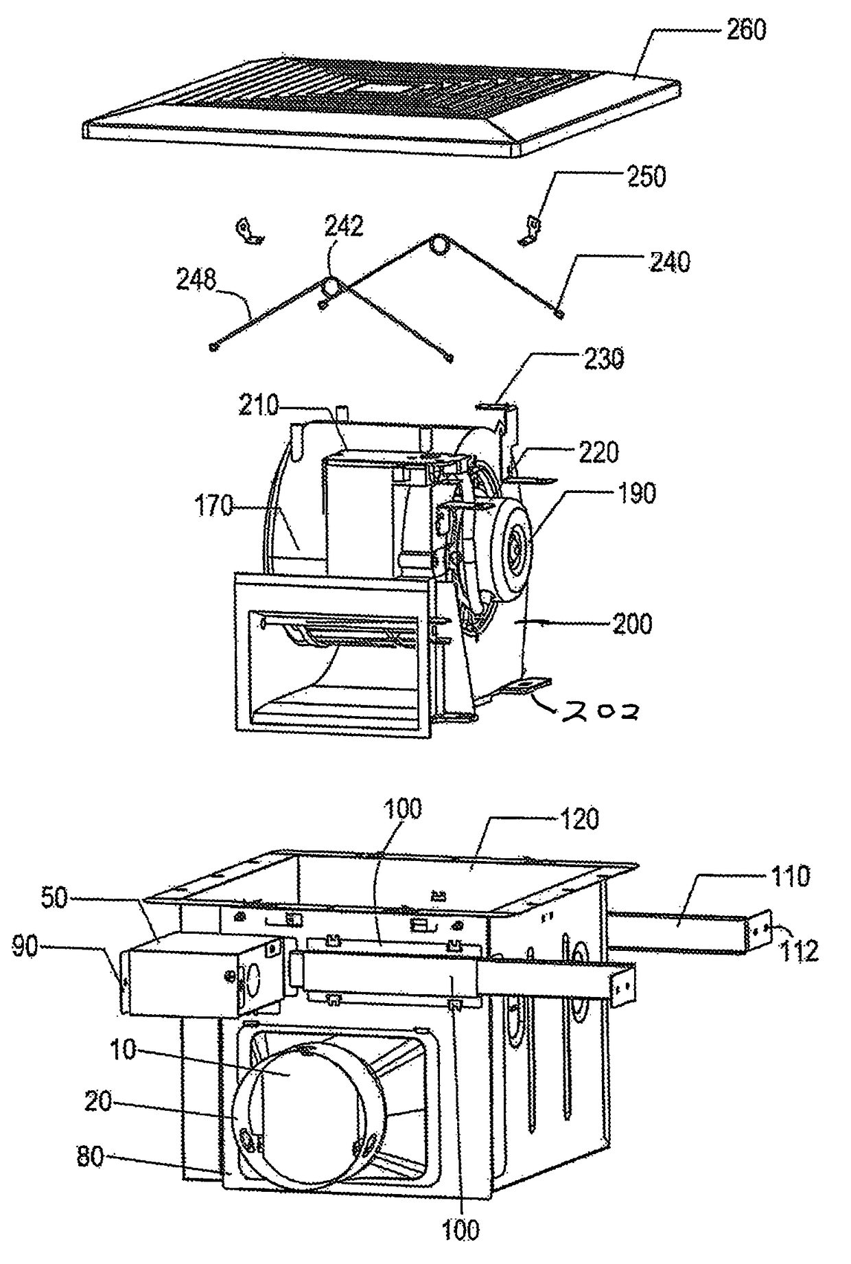
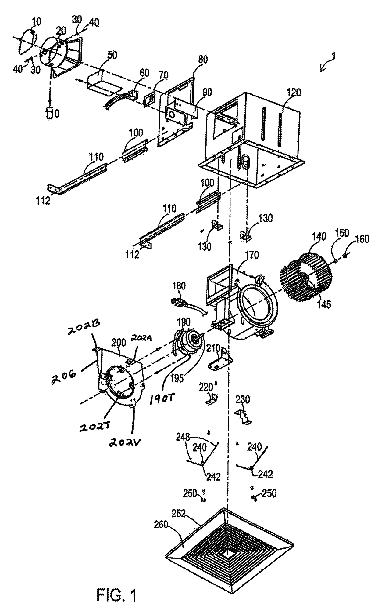
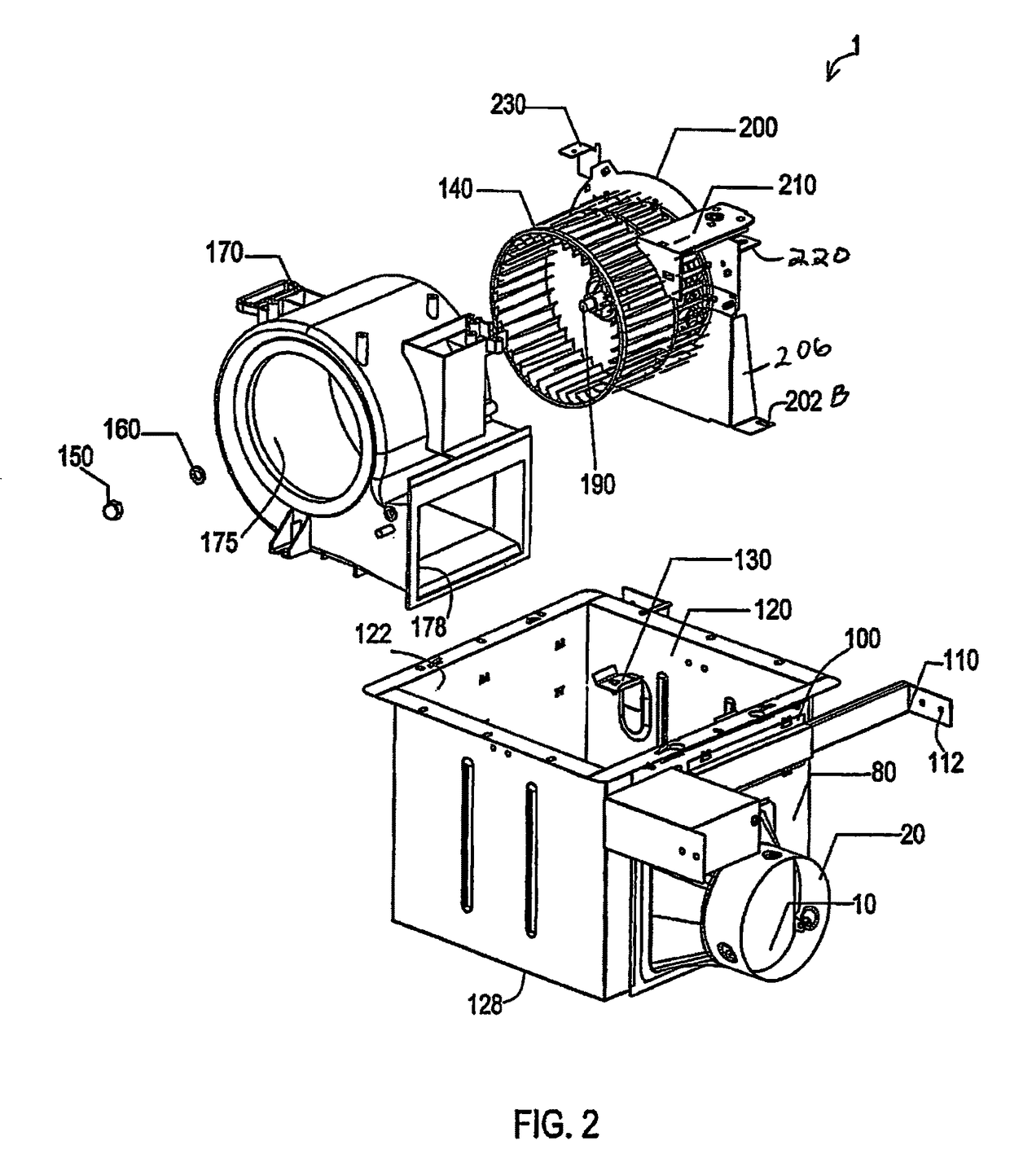
80/90 CFM bath fan with telescoping side extension brackets and side by side motor and blower wheel
a technology of exhaust fans and telescoping brackets, which is applied in the direction of ventilation systems, heating types, lighting and heating apparatus, etc., can solve the problems of difficult installation of bath fans into ceilings, difficult centering of bath fans in rooms, and many bath fans that are difficult to be installed into ceilings. achieve the effect of improving airflow
- Summary
- Abstract
- Description
- Claims
- Application Information
AI Technical Summary
Benefits of technology
Problems solved by technology
Method used
Image

Examples
embodiment 270
[0112]FIG. 12 is an exploded perspective view of an embodiment 270 of an 80 CFM bath fan housing (with no heater) 120, telescoping side extension brackets 110, side by side motor 190 and blower wheel 140, with a light 271. FIG. 13 is an assembled perspective view with partial cut-away along one side of the 80 CFM bath fan housing 120 of FIG. 12 with removable light shade / cover 290. FIG. 14 is another assembled perspective view along another side of the 80 CFM bath fan housing 120 with light / shade cover 290 of FIG. 13. FIG. 15 is still another assembled perspective view along still another side of the 80 CFM bath fan housing 120 with light shade / cover 290 of FIG. 13.
[0113]Referring to FIGS. 12-15, the bath fan with light embodiment 270 includes similar components to the previous embodiment described, with the differences of using a light source 270, such as a 13 W CFL bulb that is attached to a socket 272 such as a GU 24 socket that can be mounted by fasteners in a protective metal l...
embodiment 400
[0140]Referring to FIGS. 17-21, the 90 CFM bath fan embodiment 400 can include basic components similar to those described in the previous embodiments, with different light components 410-470 and 530-580. Covering the top opening of the main housing 120 can be a grill bracket 580 having bent ends that can be attached to inner sides of the main housing 120 by fasteners, and the like. The closed bottom 576 of a circular grill frame 570 can be attached to an upper portion of the grill mounting bracket 580 by additional fasteners, and the like. On the outer perimeter of the grill frame 570 can be vent openings 573. Light sockets 540, 550 can be mounted to the floor 576 of the grill frame 570 by socket brackets 460, with the electrical connection ends protected by cloak wire cover(s) 450. Inside of the sockets 540, 550 can be removable light sources 530, such as but not limited to GU24 bulbs, and the like.
[0141]An elongated connect screw 430 can have a bottom end screwably attached to a ...
PUM
 Abstract
Description
Claims
Application Information