Curvature restraining member and power feeding device

a curvature restraining member and curvature technology, applied in the direction of electrical/fluid circuit, electrical apparatus, vehicle components, etc., can solve the problems of deterioration of the outward appearance of the vehicle, easy damage to the wire harness, etc., to suppress correct the bending habit of the electric wire, suppress the effect of the excessive curvature of the wire harness

Active Publication Date: 2017-12-12
YAZAKI CORP
View PDF43 Cites 2 Cited by
  • Summary
  • Abstract
  • Description
  • Claims
  • Application Information

AI Technical Summary

Benefits of technology

[0006]Therefore, the above-described problem is focused, and the object of the present invention is to provide a curvature restraining member capable of suppressing an excessive curvature of the wire harness, and capable of suppressing a bending habit of electric wires when the wire harness is extended after it is curved, and to provide a power feeding device to which the curvature restraining member is applied.
[0013]According to the inventions described in the first to sixth aspects, by the curved portion extending from one end of the body portion, the wire harness is restrained from curving in the curving direction with the radius of curvature smaller than that of the curved portion. When the wire harness is bent back in the direction opposite from the curving direction and is extended, the electric wire in the wire harness is guided in the curving direction by the curved portion and is bent back. Even if the electric wire has the bending habit when the wire harness is curved, the curved shape in the bending habit of the electric wire is reformed by bending back in the direction opposite from the guiding direction to the curving direction by the curved portion. That is, when the wire harness is extended, the bending habit of the electric wire is corrected. According to the invention described in the first aspect, excessive curvature of the wire harness is suppressed, and it is possible to suppress the bending habit of the electric wire when the wire harness is extended after it is curved.
[0014]According to the invention described in the second aspect, since the cylinder is formed of the body portion and the lid, it is possible to enhance the strength against an external force applied to the body portion when the wire harness is bent.
[0015]According to the invention described in the third aspect, it is possible to further enhance the strength against an external force applied to the body portion by the first ribs and the second ribs which are arranged in the line.
[0016]According to the invention described in the fourth aspect, by fitting the first ribs and the second ribs into the groove formed in the inner surface of the flexible tube, it is possible to prevent the curvature-restraining member from rotating in an inner peripheral direction of the flexible tube.
[0017]According to the invention described in the fifth aspect, the flexible portion connected to one end of the curved portion which is opposite from the body portion is connected to the curved portion through the hinge such that the flexible portion can curve up to a curved shape which is continuous with the curved portion, but cannot curve when it has a curved shape which is smaller than the former curved shape, and the flexible portion has such flexible property that the flexible portion can curve. According to this, an outlying portion from the curved portion can curve, but the wire harness is restrained from curving with a radius of curvature smaller than the reference radius of the wire harness. Therefore, according to the invention described in the fifth aspect, it is possible to further suppress the excessive curve of the wire harness.

Problems solved by technology

Here, if the wire harness is excessively curved with a too small radius of curvature, there is fear that the wire harness is prone to be damaged.
Such a convex-curved wire harness inward of the vehicle is prone to attract passenger's attention, and there is fear that outward appearance in the vehicle is deteriorated.

Method used


Image

  • Curvature restraining member and power feeding device
  • Curvature restraining member and power feeding device
  • Curvature restraining member and power feeding device

Examples


Embodiment Construction

[0025]A curvature-restraining member and a power-feeding device according to an embodiment of the present invention will be described with reference to FIGS. 1 to 7A and 7B.

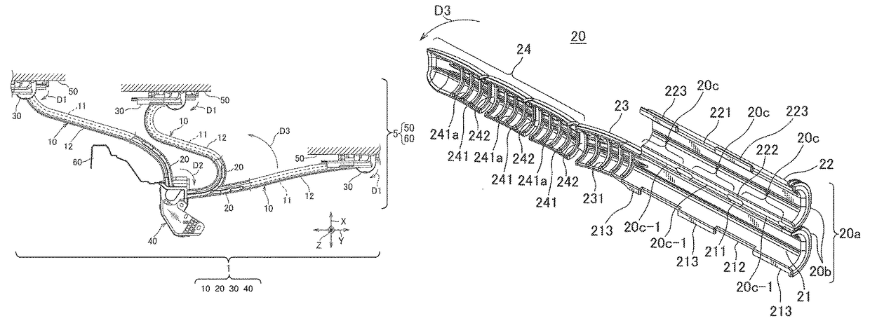
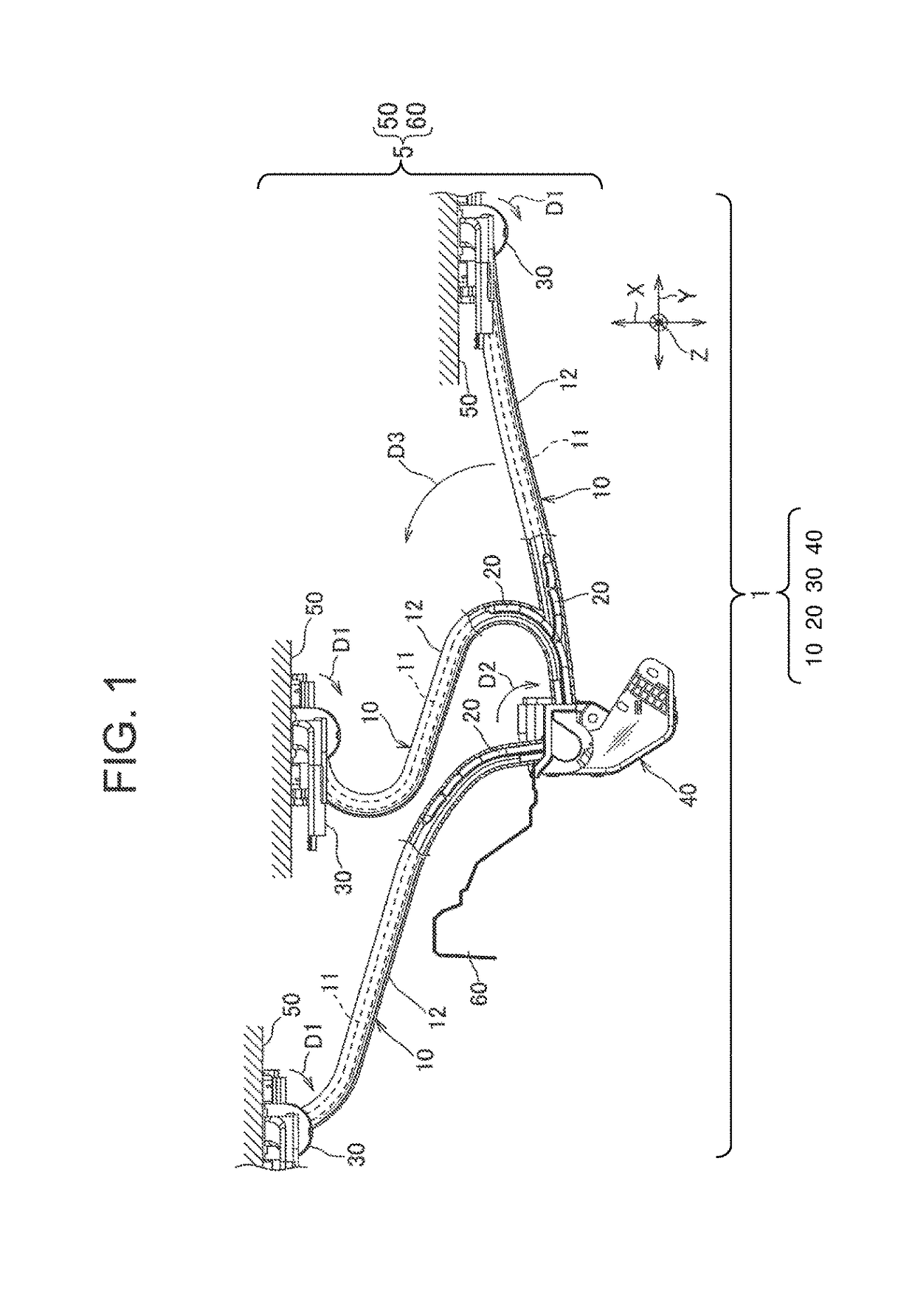
[0026]FIG. 1 is a diagram showing the power-feeding device to which the curvature-restraining member of one embodiment of the present invention is applied. The power-feeding device 1 of the embodiment electrically connects a vehicle body 60 and a sliding door 50 to each other through a wire harness 10 in a vehicle 5 having the sliding door 50. In FIG. 1, a right side therein corresponds to a front side of the vehicle 5, a left side corresponds to a rear side of the vehicle 5, an upper side corresponds to an outer side of the vehicle, and a lower side corresponds to an inner side of the vehicle. A vertical direction in the drawing is an X direction in the embodiment, a lateral direction in the drawing is a Y direction in the embodiment, and a direction perpendicular to a sheet surface is a Z direction.

[0027]In the...


PUM


Abstract

A curvature-restraining member and a power feeding device include a wire harness having an electric wire and a corrugated tube (flexible tube). The curvature-restraining member restrains the wire harness from curving in a predetermined curving direction D3 with a radius of curvature smaller than a reference radius. The curvature restraining member includes a body portion placed near at least one of ends of the corrugated tube and extending in a length direction of the electric wire, and a curved portion extending from one end of the corrugated tube opposite from the former end, and curving in the curving direction D3 with a radius of curvature not less than the reference radius with such a length that it falls within the straightly extending corrugated tube.

Description

BACKGROUNDTechnical Field[0001]The present invention relates to a curvature-restraining member for restraining an excessive curvature of a wire harness having electric wires and a flexible tube through which the electric wire is inserted, and to a power-feeding device to which the curvature-restraining member is applied.Related Art[0002]In a vehicle having a sliding door, there is a conventionally known power-feeding device which electrically connects a vehicle body and the sliding door to each other through a wire harness (see JP 2009-273312 A for example). According to this power-feeding device, the wire harness is held so that when the sliding door opens or closes, the wire harness can follow the sliding door and move in spontaneity.[0003]Here, as a configuration to hold the wire harness as described above in the power feeding device, there is proposed a configuration that the wire harness is held by a swinging member capable of swinging around a swinging shaft which is parallel ...

Claims


Application Information

Patent Timeline
Patent Type & Authority Patents(United States)
IPC IPC(8): H02G3/04B60R16/027
CPCB60R16/027H02G3/0462
Inventor TERADA, TOMOYASUSEKINO, TSUKASAYAMASHITA, HIROSHIOTSUKA, TATSUYA
Owner YAZAKI CORP
Why Eureka
Try Eureka