Surgical stapling loading unit having articulating jaws

a technology of stapling loading and articulating jaws, which is applied in the field of surgical instruments, can solve the problems of inconsistent suturing, difficult closure of the remaining vaginal cuff, and both methods requiring surgical skill and tim

a technology of stapling loading and articulating jaws, which is applied in the field of surgical instruments, can solve the problems of inconsistent suturing, difficult closure of the remaining vaginal cuff, and both methods requiring surgical skill and tim

US9855040B2Active Publication Date: 2018-01-02TYCO HEALTHCARE GRP LP

Image

  • Surgical stapling loading unit having articulating jaws
  • Surgical stapling loading unit having articulating jaws
  • Surgical stapling loading unit having articulating jaws

Examples


Embodiment Construction

[0072]Embodiments of the present disclosure are now described in detail with reference to the drawings in which like reference numerals designate identical or corresponding elements in each of the several views. As used herein, the term “clinician” refers to a doctor, a nurse, or any other care provider and may include support personnel. Throughout this description, the term “proximal” refers to the portion of the device or component thereof that is closest to the clinician and the term “distal” refers to the portion of the device or component thereof that is farthest from the clinician.

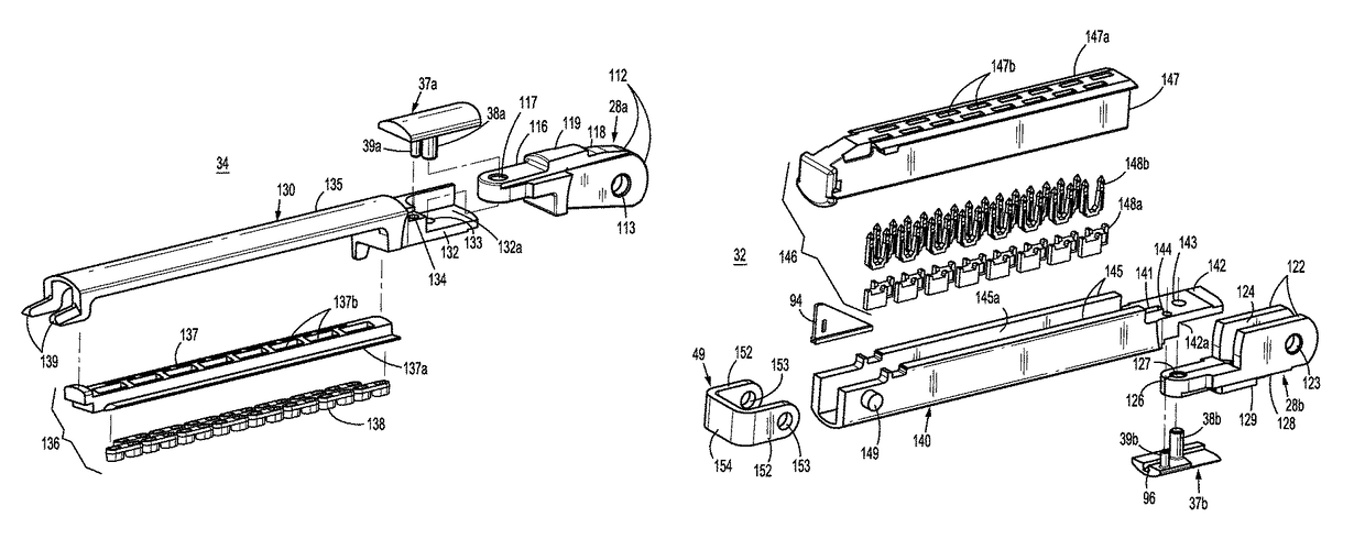
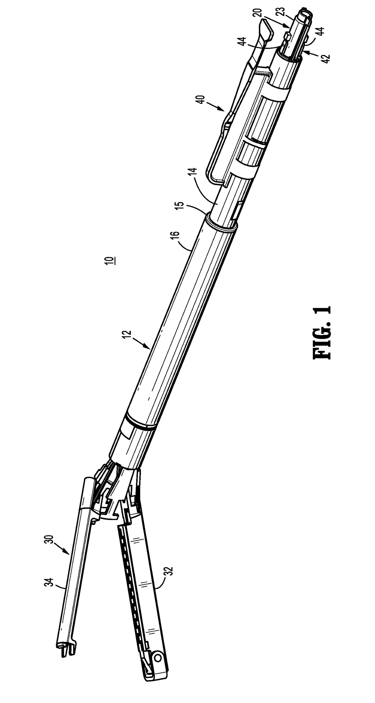
[0073]This disclosure relates generally to a loading unit for a powered or manual surgical handle, or for use with a robotic surgical system, including an articulatable end effector for joining tissue with a substantially parallel closure. The end effector is articulatable relative to an elongated body of the loading unit and includes a retainer jaw and a fastener jaw that are moveable relative to on...


PUM


Abstract

An end effector includes first and second jaw members that are pivotable relative to one another between open and clamped configurations about a pivot axis. The first and second jaw members each define a pivot hole which defines the pivot axis. The first and second jaw members also each define an articulation axis that is orthogonal to the pivot axis and position distal of the pivot axis. The first and second jaw members are articulatable about the articulation axis between straight and fully articulated configurations.

Description

BACKGROUND[0001]1. Technical Field[0002]The present disclosure relates to surgical instruments and, more specifically, to surgical stapling loading units having articulating jaws.[0003]2. Discussion of Related Art[0004]During hysterectomy procedures, such as total laparoscopic hysterectomy (TLH) procedures, the uterus and cervix are removed, creating an approximately circular structure at end of the vaginal canal called the vaginal cuff. The closure of the remaining vaginal cuff can be one of the most challenging aspects of the procedure. It is also considered to be one of the barriers to adoption of laparoscopic surgery to those trained in open procedures.[0005]After the uterus is removed it is necessary to close the vaginal cuff while avoiding dehiscence, which is when a wound ruptures along a surgical suture. Currently the vaginal cuff closure is done manually by suturing the cuff with needle and suture or with a stitching surgical instrument. Both methods require surgical skill ...

Claims


Application Information

Patent Timeline
02 Jan 2018
Publication
US9855040B2
IPC
A61B17/068; A61B17/072; A61B17/42; B25J15/00; A61B17/29; A61B17/00
CPC
A61B17/068; A61B17/07207; A61B17/42; B25J15/0019; B25J15/0028; A61B17/00234; A61B2017/4216; A61B2017/0046
Inventors
KOSTRZEWSKI, STANISLAW