A seat tube for a new energy vehicle

A new energy vehicle and seat technology, which is applied in special positions of vehicles, vehicle seats, vehicle parts, etc., can solve the problem that the seat installation structure is not suitable for the use of new energy vehicles, so as to reduce production costs and processing procedures, guarantee Structural strength, avoiding the effect of articulation

Active Publication Date: 2020-11-17
东营市大学科技园发展有限责任公司
View PDF9 Cites 0 Cited by
  • Summary
  • Abstract
  • Description
  • Claims
  • Application Information

AI Technical Summary

Problems solved by technology

[0002] New energy vehicles refer to the use of unconventional vehicle fuel as a power source, and are becoming more and more popular due to their advantages of environmental protection and energy saving. Among them, new energy vehicles that use the electricity generated by on-board battery devices as power are well received. The battery needs to be installed, so the seat installation structure of traditional cars is not suitable for new energy vehicles

Method used


Image

  • A seat tube for a new energy vehicle
  • A seat tube for a new energy vehicle
  • A seat tube for a new energy vehicle

Examples


no. 1 approach

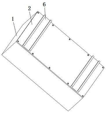
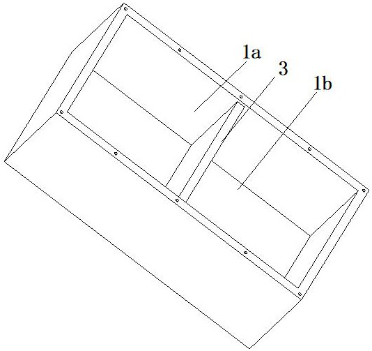
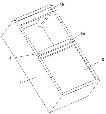
[0025] First embodiment: the present invention provides a seat tube for new energy vehicles through improvement, such as Figure 1-Figure 6 As shown, it includes a seat, and also includes a box body 1 and a box cover 2. The box cover 2 is overlapped on the top of the box body 1. The box body 1 is vertically arranged and the opening of the box body 1 is set upward. A partition 3 arranged vertically is arranged inside the box body 1, and the space in the box body 1 is divided by the partition plate 3 into a first accommodation chamber 1a and a second accommodation chamber 1b, and the first accommodation chamber 1a is provided with a A first support assembly 4 for supporting the case cover 2, a second support assembly 5 for supporting the case cover 2 is provided in the second accommodating cavity 1b, and the bottom of the case cover 2 is embedded in the case body 1 And the top of the case cover 2 is provided with a positioning seat 6 for fixing the seat. When the seat tube needs...

no. 2 approach

[0031] The second embodiment: a seat tube for a new energy vehicle. The new energy vehicle includes a seat, including a box body 1 and a box cover 2. The box cover 2 is overlapped on the top of the box body 1, and the box body 1 The box body 1 is arranged vertically and the opening of the box body 1 faces upwards. A vertical partition 3 is arranged inside the box body 1. The partition board 3 divides the space in the box body 1 into a first accommodating cavity 1a and a second accommodating chamber 1a. The accommodating chamber 1b, the first accommodating chamber 1a is provided with a first support assembly 4 for supporting the case cover 2, and the second accommodating chamber 1b is provided with a second support assembly for supporting the case cover 2 5. The bottom of the box cover 2 is embedded in the box body 1 and the top of the box cover 2 is provided with a positioning seat 6 for fixing the seat. The first storage chamber 1a and the second storage chamber 1b are respect...


PUM


Abstract

The invention relates to the field of new energy sources, in particular to a seat barrel for a new energy vehicle, which includes a seat, a tank body and a tank cover; a lid of that box is overlappedon the top of the box body, the box body is vertically arranged and the opening of the box body is arranged upward, the box body is provided with a partition plate vertically arranged, the partition plate divides the space in the box into a first accommodation cavity and a second accommodation cavity, the first accommodating cavity is provided with a first supporting assembly for supporting the box cover, the second accommodating cavity is provided with a second supporting assembly for supporting the box cover, the bottom of the box cover is embedded in the box body, and the top of the box cover is provided with a positioning seat for fixing the seat. The invention has the beneficial effect that the interior space of the new energy vehicle is fully utilized, the structural strength of theseat barrel is ensured, and the battery is protected.

Description

technical field [0001] The invention relates to the field of new energy, in particular to a seat tube for a new energy vehicle. Background technique [0002] New energy vehicles refer to the use of unconventional vehicle fuel as a power source, and are becoming more and more popular due to their advantages of environmental protection and energy saving. Among them, new energy vehicles that use the electricity generated by on-board battery devices as power are well received. The battery needs to be installed, so the seat installation structure of the traditional car is not suitable for the use of new energy vehicles. Contents of the invention [0003] The object of the present invention is to provide a seat tube for a new energy vehicle to solve the problems raised in the above-mentioned background technology. [0004] The technical solution of the present invention is to include a seat, a box body and a box cover, the box cover is overlapped on the top of the box body, the...

Claims


Application Information

Patent Timeline
Patent Type & Authority Patents(China)
IPC IPC(8): B60N2/90B60K1/04
CPCB60K1/04B60N2/90
Inventor 陈志军
Owner 东营市大学科技园发展有限责任公司
Why Eureka
Try Eureka