Structure of button for electronic product

Inactive Publication Date: 2005-03-01
PATEN WIRELESS TECH
View PDF10 Cites 32 Cited by
  • Summary
  • Abstract
  • Description
  • Claims
  • Application Information

AI Technical Summary

Benefits of technology

Accordingly, in the view of the foregoing, the present inventor makes a detailed study of related art to evaluate and consider, and uses years of accumulated experience in this field, and through several experiments, to create a structure of a button for electronic products. The present invention provides an innovated cost effective structure of a button for electronic products, which structure can fit for a variety of electronic products that fit in the present trend of being lighter, thinner, shorter and smaller.
According to an aspect of the present invention, the length of the positioning bar is adapted to limit the distance between the upper lid and the chassis, and therefore the distance between the upper lid and the chassis can be adjusted by adjusting the length of positioning bar. In other words, for applying the structure of the button of the present invention an electronic product of a particular specification, the positioning bar of a desirable length can be selected to meet the specification of the electronic pr

Problems solved by technology

However, there are several defects with the conventional scissors structure, the buttons for the scissors structure and the installation method described as follows.1. The first and second supporting racks A and B of the conventional buttons have a fixed the moving distance

Method used


Image

  • Structure of button for electronic product
  • Structure of button for electronic product
  • Structure of button for electronic product

Examples


Example

Reference will be made in detail to the preferred embodiments of the invention, examples of which are illustrated in the accompanying drawings. Wherever possible, the same reference numbers are used in the drawings and the description to refer to the same or like parts.

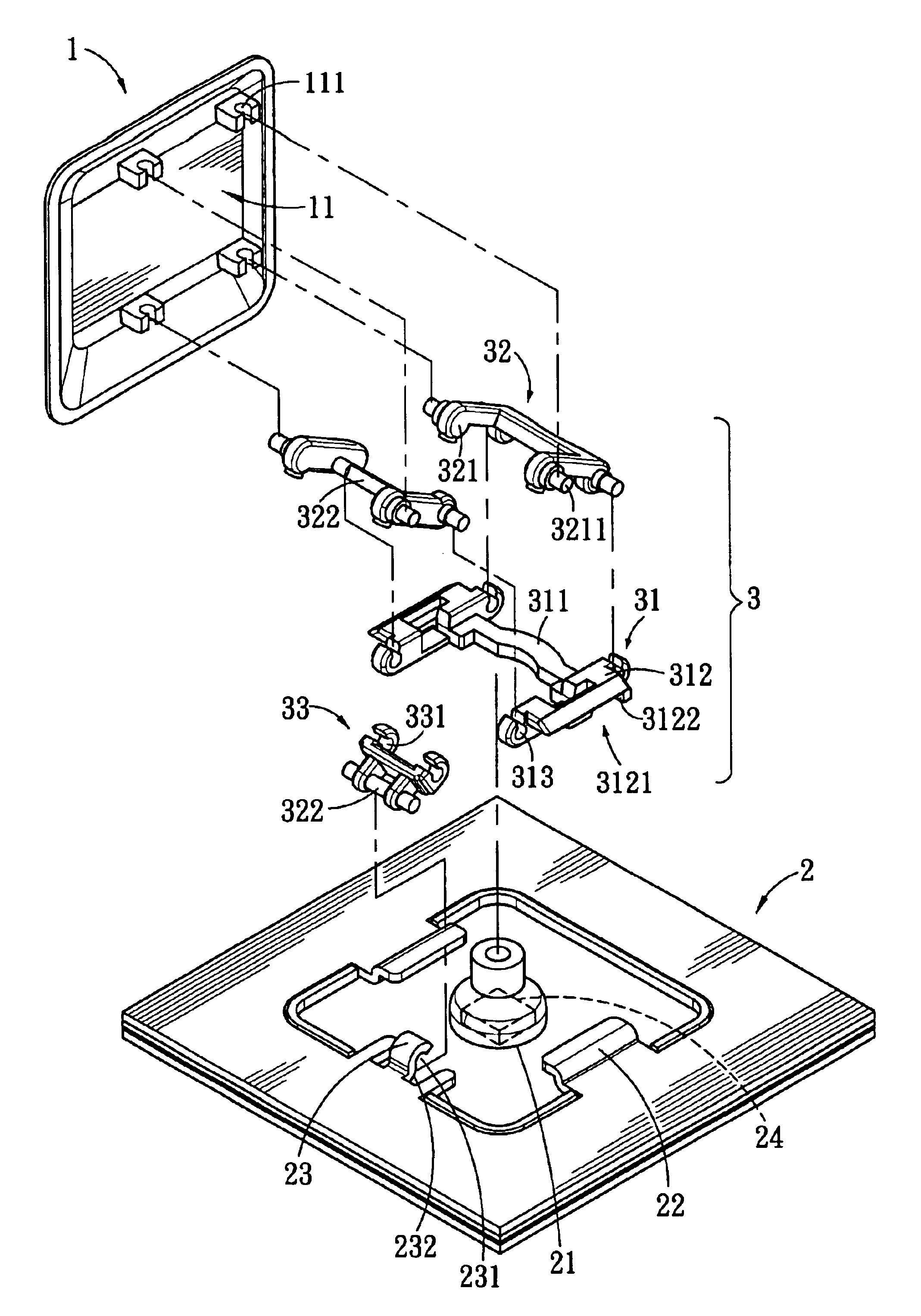
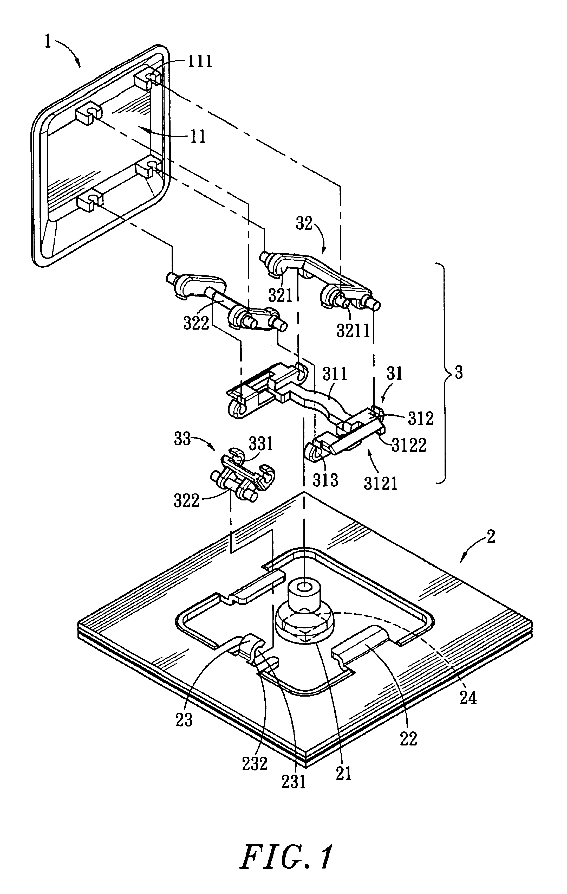
In FIG. 1, an exploded view of a structure of a button for an electronic product according to a preferred embodiment of the present invention is shown. The structure of the button comprises an upper lid 1, a chassis 2 and a parallel bar set 3.

A receiving space 11 having a plurality of protruded axial holes 111 is formed above upper lid 1.

A switch 24 is disposed on a surface of the chassis 2, wherein the switch 24 is covered by a resilient element 21. The switch 24 comprises tracks 22 on the two sides thereof. Each track 22 has an open buckling element 23 set on a side of a buckling groove 231 is formed, and the buckling groove 231 is conjoint to a sliding face 232.

The parallel bar set 3 comprises a base 31 having a bo...


PUM


Abstract

A structure of button for an electronic product has an upper lid, a chassis having a switch and a parallel bar set, which positioned between the upper lid and the chassis, such that the upper lid can move down upon being depressed by an external force to activate the switch of the chassis and can substantially return to its original position upon removing the external force. The parallel bar set has a base, two supporting racks, positioned parallel to each other above the base, wherein a side of one of the two supporting racks is connected to a positioning bar and the positioning bar is buckled to the base, the positioning bar and two supporting racks are positioned between the chassis and the upper lid to enable the upper lid to move towards the chassis under the influence of a movement of the parallel bar set.

Description

BACKGROUND OF THE INVENTION1. The Field of the InventionThe present invention relates to a structure of button for an electronic product, and more particularly to a structure of button comprising a parallel bar set positioned between an upper lid and a chassis such that the length of a positioning bar of the parallel bar set limits the moving distance between the lid and the chassis.2. Description of Related ArtPresently, the well-developed electronic technology produced advanced electronic products that provide convenience in our daily activities. Most electronic products require an input device for enabling the user to input letters, numbers or commands enjoy the functions provided by the electronic products. Examples of such input devices include mouse, keyboard or joystick and light beam gun for games. The development of these products later led to development, for instance, from buttons on the keyboard for the conventional desktop computer to the buttons for the notebook comput...

Claims


Application Information

Patent Timeline
IPC IPC(8): H01H3/02H01H3/12
CPCH01H3/122
Inventor WANG, YUNG-HUI
Owner PATEN WIRELESS TECH
Why Eureka
Try Eureka