Control apparatus for giving notification of maintenance and inspection times of signal-controlled peripheral devices

a technology of signal-controlled peripheral devices and control apparatus, which is applied in the direction of computer control, program control, instruments, etc., can solve the problems of not being able to check individual components at the optimum timing for each, and affecting the service life of components

Active Publication Date: 2018-03-06
FANUC LTD
View PDF15 Cites 2 Cited by
  • Summary
  • Abstract
  • Description
  • Claims
  • Application Information

AI Technical Summary

Benefits of technology

[0009]It is therefore an object of the present invention to provide a control apparatus that can give proper notification of the times of maintenance and inspection of peripheral devices that constitute an automated system, without adding an extra device.

Problems solved by technology

However, the intervals of maintenance and inspection are not the same so it is difficult for the user to know the timings of maintenance and inspection for different devices.
In what is assumed to be the usual method, whereby maintenance and inspection is performed at constant intervals, it is not possible to check individual components at the optimum timing for each of them.
In other words, there is a risk or possibility that some components have already reached the end of their service life while others unnecessarily undergo maintenance and inspection.
However, the components that constitute an automated system are not always controlled by a controller including a processor and storage as in the robot or machine tool, but there are many peripheral devices that operate in accordance with the signals from the control apparatus of the robot or machine tool.
In order for each of these peripheral devices to add up the actual time of operation and measure and record the state quantity, it is necessary to provide an additional device, hence such functions are not easy to implement.

Method used


Image

  • Control apparatus for giving notification of maintenance and inspection times of signal-controlled peripheral devices
  • Control apparatus for giving notification of maintenance and inspection times of signal-controlled peripheral devices
  • Control apparatus for giving notification of maintenance and inspection times of signal-controlled peripheral devices

Examples


first embodiment

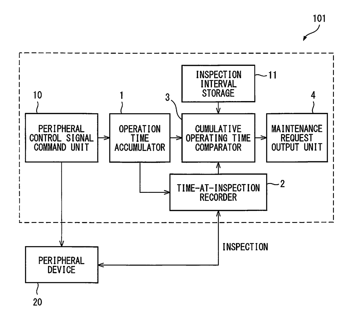
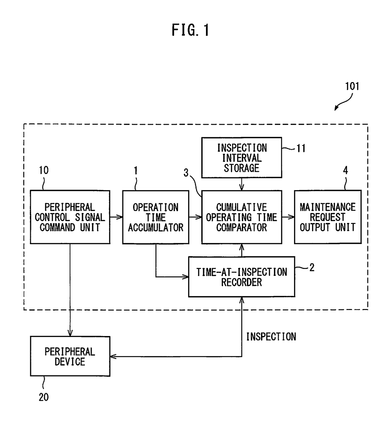
[0019]A control apparatus according to a first embodiment of the present invention will be described. FIG. 1 is a block diagram showing a control apparatus according to the first embodiment of the present invention. A control apparatus 101 according to the first embodiment of the present invention is a control apparatus for use in an automaton that operates in cooperation with a peripheral device 20 on the basis of signal input and output, and includes an operating time accumulator 1 which, by regarding the output time of a control signal to the peripheral device 20 or the output time of an operating signal from the peripheral device 20, as operating time, determines cumulative operating time by adding up the operating times; a time-at-inspection recorder 2 that records the cumulative operating time when inspection is performed, as the cumulative operating time at inspection; a cumulative operating time comparator 3 that compares the difference between the current cumulative operati...

second embodiment

[0032]Next, a control apparatus according to a second embodiment of the present invention will be described. FIG. 3 is a block diagram showing a control apparatus according to the second embodiment of the present invention. A control apparatus 102 according to the second embodiment of the present invention is a control apparatus for use in an automaton that operates in cooperation with a peripheral device 20 on the basis of signal input and output, and includes an operation count accumulator 5 which, by regarding the number of times of outputting a control signal to the peripheral device 20 or the number of times of outputting an operation signal from the peripheral device 20, as the count of operations, determines the cumulative operation count by adding up the count of operations; an operation count-at-inspection recorder 6 that records the cumulative operation count at the time of inspection as the cumulative operation count at inspection; a cumulative operation count comparator ...

third embodiment

[0045]Next, a control apparatus according to a third embodiment of the present invention will be described. FIG. 5 is a block diagram showing a control apparatus according to the third embodiment of the present invention. A control apparatus 103 according to the third embodiment of the present invention is a control apparatus for use in an automaton that operates in cooperation with a peripheral device 20 on the basis of signal input and output and records a state quantity that varies with the operation of the peripheral device 20, and includes a state-at-inspection recorder 8 that records the state quantity at the time of inspection as the state quantity at inspection; a state quantity comparator 9 that compares the difference between the current state quantity and the state quantity at inspection, i.e., the variation of the state quantity from the latest inspection or the variation of the state quantity after inspection, with a preset inspection-required variation of the state qua...


PUM


Abstract

A control apparatus in an automaton that operates in cooperation with a peripheral device, includes: an operating time accumulator regarding the output time of a control signal to the peripheral device or the output time of an operating signal from the peripheral device as operating time and determining cumulative operating time by adding up the operating times; a time-at-inspection recorder recording the cumulative operating time when inspection is performed as the cumulative operating time at inspection; a cumulative operating time comparator comparing the difference between the current cumulative operating time and the cumulative operating time at inspection, the cumulative operating time from the latest inspection, or the cumulative operating time after inspection, with a preset inspection interval; and, a maintenance request output unit outputting a maintenance request to the outside when the cumulative operating time after inspection obtained as a result of the comparison exceeds the preset inspection interval.

Description

RELATED APPLICATIONS[0001]The present application claims priority to Japanese Patent Application Number 2015-035853, filed Feb. 25, 2015, the disclosure of which is hereby incorporated by reference herein in its entirety.BACKGROUND OF THE INVENTION[0002]1. Field of the Invention[0003]The present invention relates to a robot control apparatus, in particular, relating to a control apparatus provided with a function for giving notification of maintenance and inspection times of peripheral devices that operate in cooperation with an automaton such as a robot, machine tool or the like.[0004]2. Description of the Related Art[0005]Recently, in order to reduce unexpected downtime, functions which urge the user to perform periodical maintenance of a robot have been developed and applied. A robot operates as a system, and in most automated systems, automatons such as robots, machine tools and the like control their peripheral devices by DO (digital output) signals, etc., so as to perform oper...

Claims


Application Information

Patent Timeline
Patent Type & Authority Patents(United States)
IPC IPC(8): G05B19/042G05B19/4063
CPCG05B19/0425G05B19/4063
Inventor IKEDA, YUARITA, SOICHI
Owner FANUC LTD
Why Eureka
Try Eureka