Liquid level detection apparatus for engine oil

a technology of liquid level detection and engine oil, which is applied in the direction of liquid/fluent solid measurement, machines/engines, instruments, etc., can solve the problems of laborious wiring, prone to transient fluctuations, and low oil level surface, so as to simplify the procedure of drawing out wires and accurately give notification of low oil level

Active Publication Date: 2012-04-17
HONDA MOTOR CO LTD
View PDF10 Cites 0 Cited by
  • Summary
  • Abstract
  • Description
  • Claims
  • Application Information

AI Technical Summary

Benefits of technology

[0007]An object of the present invention is to provide an engine oil-level detection apparatus that can accurately give notification of a low oil level, and to provide an engine oil-level detection apparatus that can simplify the procedure for drawing out wires from a switch.

Problems solved by technology

Therefore, the surface level of the oil is susceptible to transient fluctuations when the engine oil 209 in the crankcase is lifted up.
Wiring is furthermore laborious in that wires must be laid out in the oil in order to draw out the wires of the reed switch 206.

Method used


Image

  • Liquid level detection apparatus for engine oil
  • Liquid level detection apparatus for engine oil
  • Liquid level detection apparatus for engine oil

Examples


Embodiment Construction

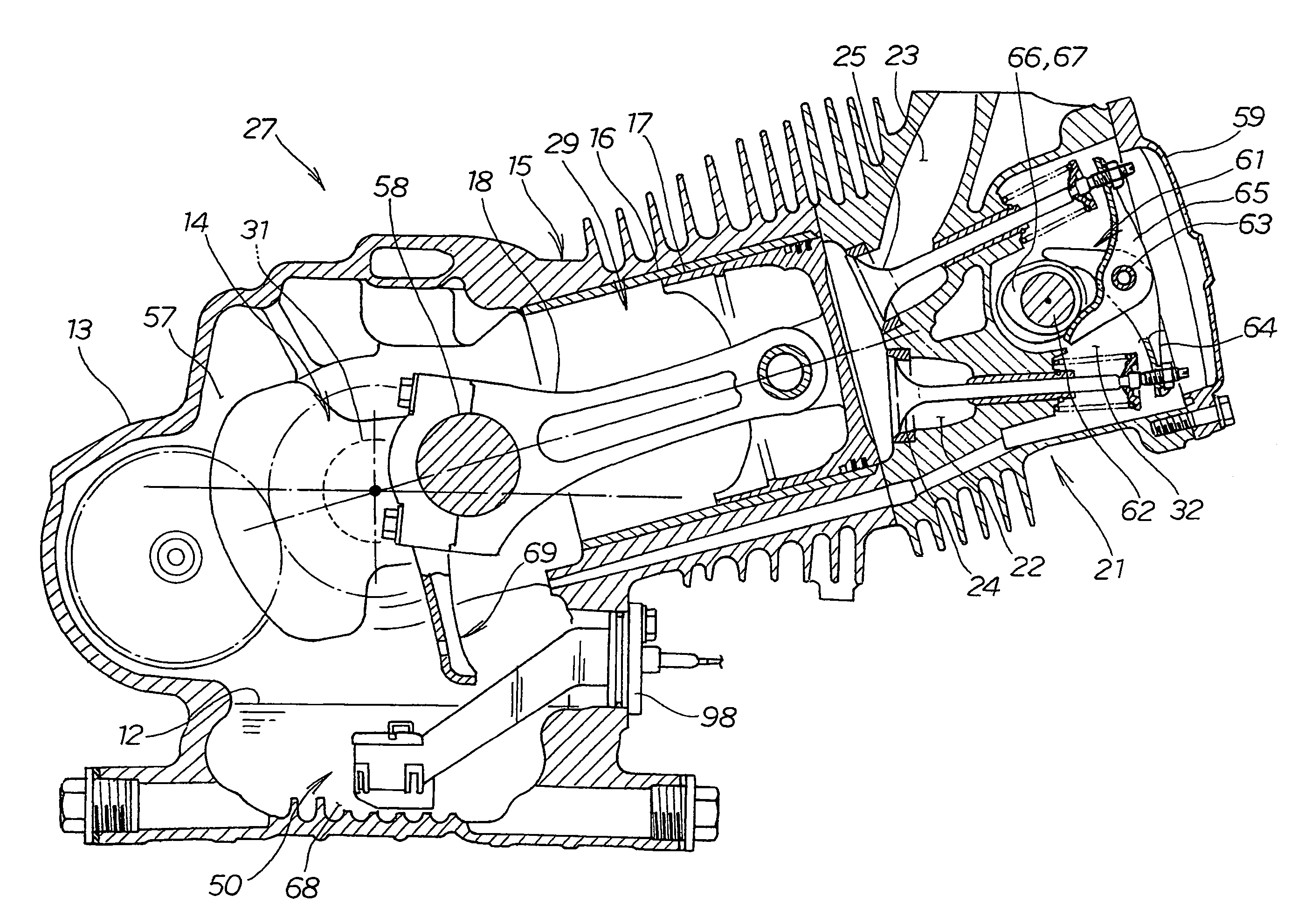
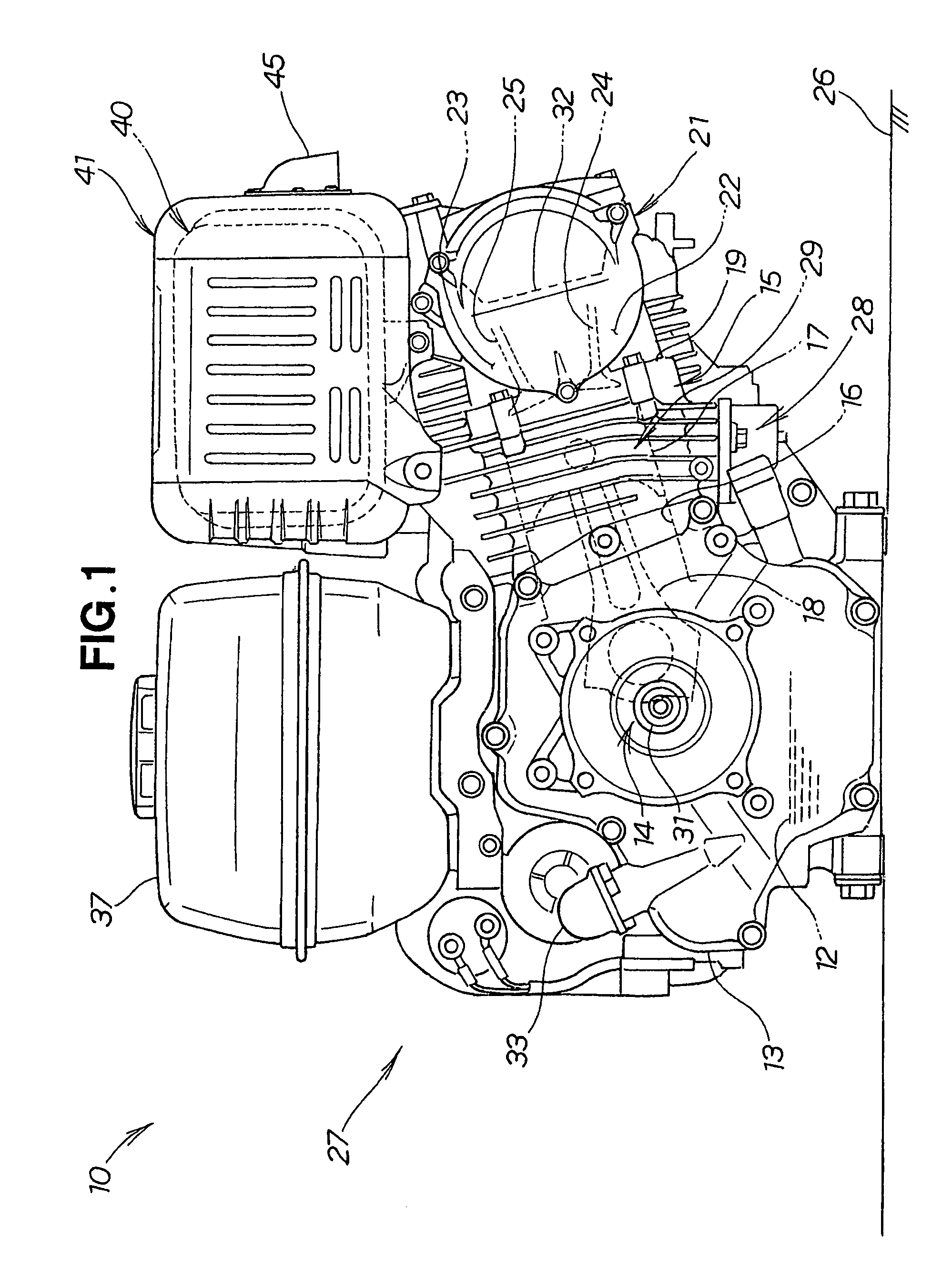
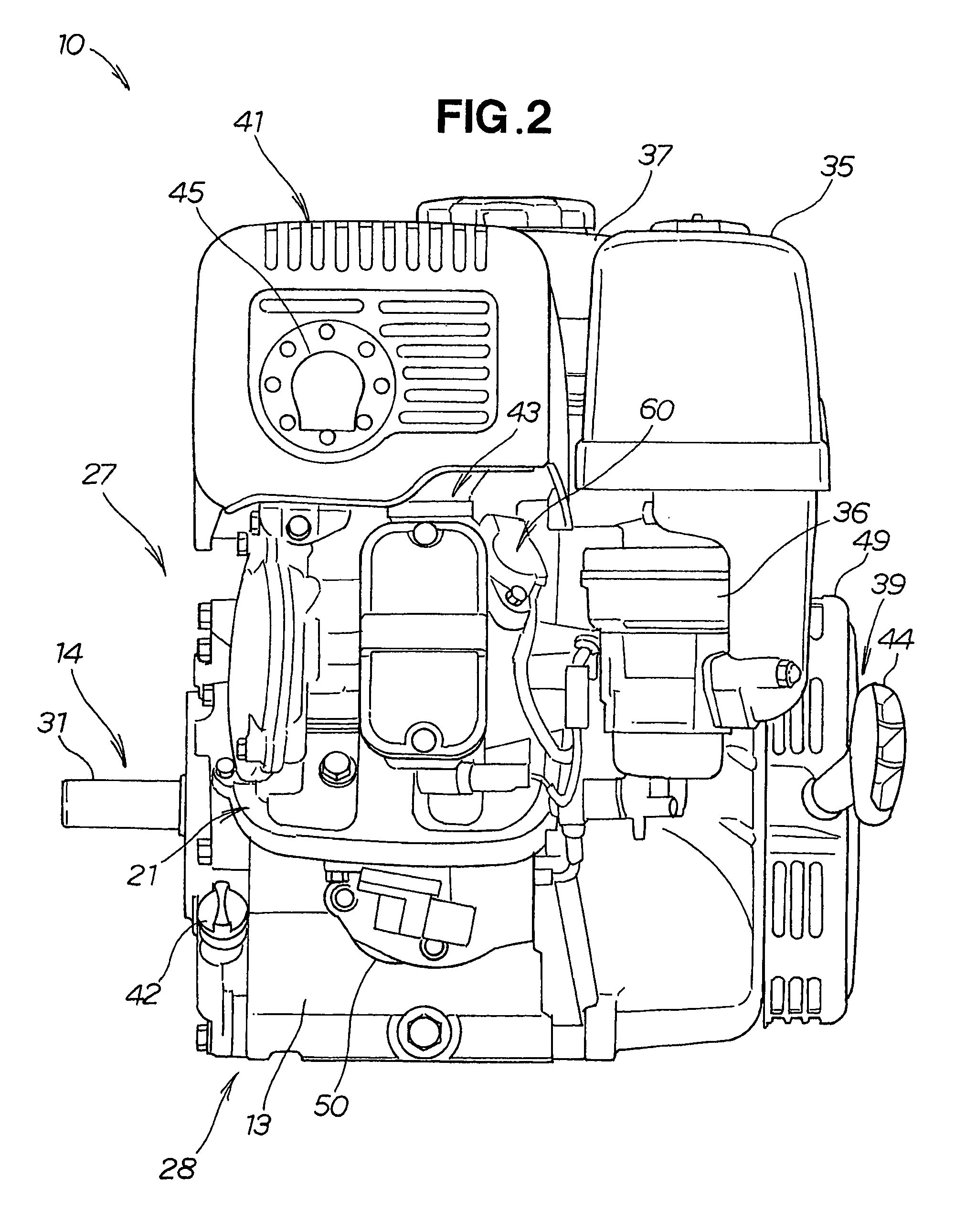
[0029]The engine unit 10 shown in FIGS. 1 to 3 has an engine main body (hereinafter simply referred to as “engine”) 27, and auxiliary equipment, which includes accessories for operating the engine 27. The auxiliary equipment principally includes an air cleaner 35 for suctioning outside air, a carburetor 36 for vaporizing and feeding fuel (gasoline) to the combustion chamber 29, a fuel tank 37 for storing fuel, a muffler 40 for reducing the exhaust noise of the exhaust gas, a recoil starter 39 for starting the engine 10, an oil-level detection apparatus (oil alert) 50 for detecting the surface of the oil, and a plug gap 60 housed in the ignition section (not shown) that is used for ignition. The engine main body 27 of the example shown in the diagrams is an overhead-camshaft (OHC) air-cooled engine with a sloped cylinder.

[0030]The engine 27 is provided with a crankcase 13 for holding engine oil 12, a crank shaft 14 as an output shaft that is horizontally and rotatably mounted on the ...


PUM


Abstract

A float-type oil-level detection apparatus is provided for detecting the surface of engine oil. A housing (81) for housing a float (82) has a through-hole (136) in the sidewall of the side opposite from the sidewall that faces the movement of the oil dipper (69).

Description

TECHNICAL FIELD[0001]The present invention relates to a detection apparatus for detecting a drop in the surface level of engine oil.BACKGROUND ART[0002]Japanese Utility Model Application Laid-open No. 56-56143 discloses an engine oil surface level detection apparatus. This level detection apparatus is described below with reference to FIG. 12.[0003]The level detection apparatus 200 shown in FIG. 12 is composed of a housing 201 whose lower portion is open, a shaft 203 that extends downward so as to be suspended from the ceiling 202 of the housing 201, a float 204 that is slidably mounted on the shaft 203, a magnet 205 provided to the float 204, a reed switch 206 housed in the shaft 203 and actuated by the approach of the magnet 205, cylindrical bushes 208 and 208 mounted on the opening formed in the side walls 207 and 207 of the housing 201, and a crankcase for holding engine oil 209.[0004]However, in the level detection apparatus 200, the side walls 207 and 207 of the housing 201 ar...

Claims


Application Information

Patent Timeline
Patent Type & Authority Patents(United States)
IPC IPC(8): G01F23/30
CPCF01M11/12G01F23/70G01F23/74G01F23/64
Inventor MATSUBARA, YASUNORINAKAMURA, TOSHIKAZUIIJIMA, YOSHIHIRO
Owner HONDA MOTOR CO LTD
Why Eureka
Try Eureka