Installation for extending an electrical wiring into a junction box

a technology for installing an electrical wiring and a junction box, which is applied in the direction of cable junctions, electrical equipment, etc., can solve the problems of reducing the service life of the end connector, unable to meet the diameter of the larger orifice, and rendering the end connector b>106/b> difficult to install, etc., to facilitate the addition of one or more electrical lines

Active Publication Date: 2018-05-08
LANGENWALTER BRANDON P
View PDF13 Cites 1 Cited by
  • Summary
  • Abstract
  • Description
  • Claims
  • Application Information

AI Technical Summary

Benefits of technology

[0009]The present invention is directed to an installation for extending an electrical wiring comprised of one or more electrical wires into a junction box, the installation comprising an electrical bushing with collar which facilitates addition of one or more electrical lines to an existing junction box when only a large orifice in the junction box is available and a matching large flex cord and flex cord end connector are not available. The electrical bushing provides an adapter which increases the overall outer diameter and the overall threaded length of the flex cord end connector, allowing the flex cord end connector to be snugly fitted into the larger orifice and to more firmly receive the threading of a nut on the interior side of the junction box. Thus, the electrical bushing allows securing a relatively smaller end connector into a relatively larger orifice and prevents the end connector from inadvertently falling from the relatively larger orifice.

Problems solved by technology

However, a flex cord end connector that is sized to match the diameter of the larger orifice 105 may not be available.
This installation technique, however, has several drawbacks.
This renders the end connector 106 difficult to install.

Method used


Image

  • Installation for extending an electrical wiring into a junction box
  • Installation for extending an electrical wiring into a junction box
  • Installation for extending an electrical wiring into a junction box

Examples


Embodiment Construction

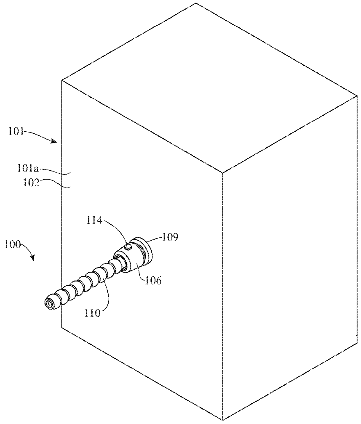
[0044]The following detailed description is merely exemplary in nature and is not intended to limit the described embodiments or the application and uses of the described embodiments. As used herein, the word “exemplary” or “illustrative” means “serving as an example, instance, or illustration.” Any implementation described herein as “exemplary” or “illustrative” is not necessarily to be construed as preferred or advantageous over other implementations. All of the implementations described below are exemplary implementations provided to enable persons skilled in the art to make or use the embodiments of the disclosure and are not intended to limit the scope of the disclosure, which is defined by the claims. For purposes of description herein, the terms “upper”, “lower”, “left”, “rear”, “right”, “front”, “vertical”, “horizontal”, and derivatives thereof shall relate to the invention as oriented in FIG. 1. Furthermore, there is no intention to be bound by any expressed or implied theo...


PUM


Abstract

An installation for extending an electrical wiring into a junction box comprises an electrical bushing including a bushing body having an outer diameter corresponding to an inner diameter of an orifice in a junction box. A bushing bore extends through the bushing. A bushing collar terminates the bushing body. Exterior bushing threads are on the bushing body adjacent to the bushing collar. In a typical junction box installation, an end connector on a flex cord may be coupled to the bushing body, for instance by threading of the end connector onto interior bushing threads in the bushing body. The electrical bushing may be inserted through and secured in an orifice in a junction box by threading a nut on the exterior bushing threads. Accordingly, the electrical bushing prevents the end connector on the flex cord from inadvertently falling from the orifice in the junction box.

Description

CROSS-REFERENCE TO RELATED APPLICATIONS[0001]This application claims the benefit of U.S. Provisional Patent Application Ser. No. 62 / 370,001, filed on Aug. 2, 2016, which is incorporated by reference herein in its entirety.FIELD OF THE INVENTION[0002]The present invention relates generally to electrical junction boxes, and more particularly, to an installation for extending an electrical wiring into a junction box, the installation comprising an electrical bushing with collar which facilitates addition of one or more electrical lines to an existing junction box when only a large orifice in the junction box is available and a matching large flex cord and flex cord end connector are not available.BACKGROUND OF THE INVENTION[0003]Electrical junction boxes are commonly used to establish and conceal electrical connections between electrical components such as lights and light switches. Junction boxes are frequently mounted in ceilings, under floors, behind access panels in domestic or com...

Claims


Application Information

Patent Timeline
Patent Type & Authority Patents(United States)
IPC IPC(8): H02G3/06H02G3/16H02G15/10H02G3/08
CPCH02G3/16H02G15/10H02G3/06H02G3/083H02G3/0683
Inventor LANGENWALTER, BRANDON P.
Owner LANGENWALTER BRANDON P
Why Eureka
Try Eureka