Clamp apparatus

a technology of clamping apparatus and clamping rod, which is applied in the direction of work holders, manufacturing tools, and surfaces, can solve the problem of not being able to take out workpieces from the clamping rod, and achieve the effect of convenient and reliable releas

Inactive Publication Date: 2018-05-15
SMC CORP
View PDF12 Cites 0 Cited by
  • Summary
  • Abstract
  • Description
  • Claims
  • Application Information

AI Technical Summary

Benefits of technology

[0006]A general object of the present invention is to provide a clamp apparatus, which is capable of easily and reliably releasing a clamped state manually, in the case that an output from a drive unit has been stopped.
[0014]According to the present invention, in the clamp apparatus, which includes the cam members on ends of the pair of clamp arms, the cam members are pressed by the pressing members of the driving force transmission mechanism under a driving action of the drive unit, so that the ends of the pair of clamp arms are rotated, whereby the workpiece is clamped. In addition, even in the case that, for some reason, the drive unit is stopped and the driving force therefrom is extinguished, since the clamped state can easily and reliably be released by the manual release means, the workpiece can assuredly be taken out and removed from the clamp apparatus.

Problems solved by technology

However, since the workpiece is kept in the clamped state by the clamp arms, in some cases, it is not possible for the workpiece to be taken out from the clamp apparatus.

Method used


Image

  • Clamp apparatus
  • Clamp apparatus
  • Clamp apparatus

Examples


Embodiment Construction

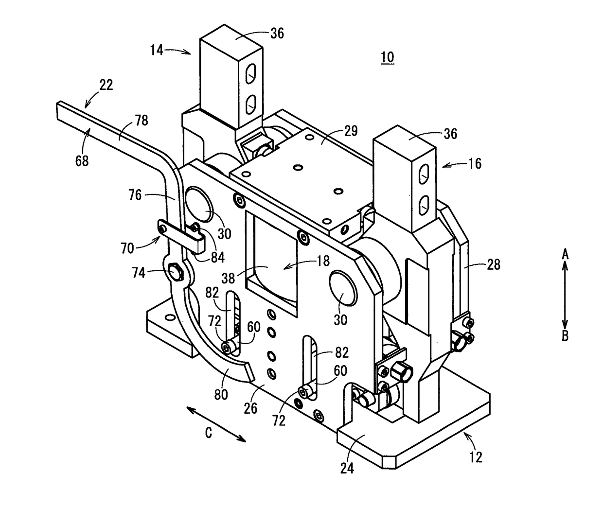
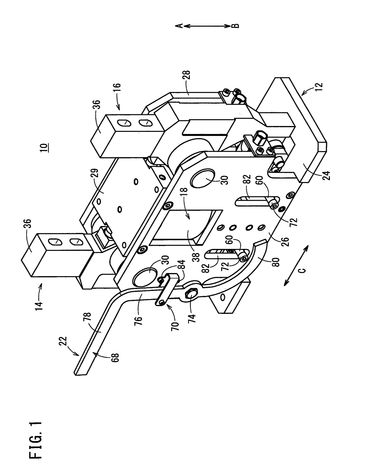
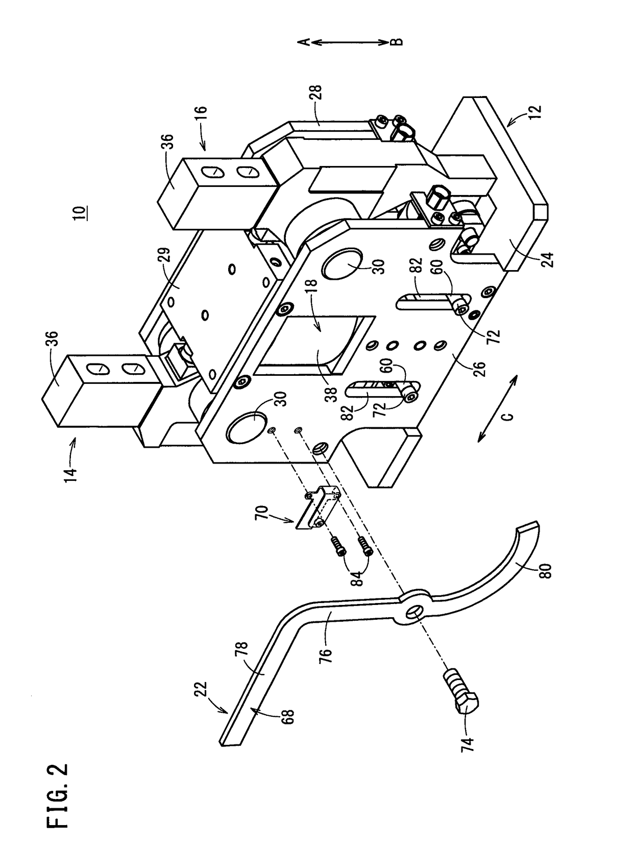
[0022]As shown in FIGS. 1 through 7, a clamp apparatus 10 includes a body 12, a pair of first and second clamp arms 14, 16 pivotally supported rotatably on the body 12, a drive unit 18 fixed to the body 12, a driving force transmission mechanism 20 that transmits driving forces of the drive unit 18 to the first and second clamp arms 14, 16, and a manual release mechanism 22, which is capable of forcibly releasing, by manual operation, the clamped state of a workpiece W that is clamped by the first and second clamp arms 14, 16.

[0023]The body 12, for example, is made up from a base 24, which is formed in a planar shape and is arranged in a horizontal direction, and a pair of first and second plate bodies 26, 28, which are connected respectively to both side surfaces of the base 24, and which are separated mutually by a predetermined distance. The first and second plate bodies 26, 28 are perpendicular to the base 24, and are formed at predetermined heights in an upward direction (the d...


PUM


Abstract

A clamp apparatus includes a pair of first and second clamp arms supported rotatably on a body. The clamp apparatus also includes a manual release mechanism capable of manually releasing a clamped state in the case that an output from a drive unit to the first and second clamp arms is stopped and the clamped state of a workpiece is locked. The manual release mechanism includes a release lever disposed rotatably on a first plate body. By an operator operating the release lever to thereby rotate the release lever, a block body of a driving force transmission mechanism is pressed and moved upwardly, and pressing forces applied to the first and second clamp arms in widthwise outside directions thereof by a pair of rollers, are released. Consequently, gripping members of the first and second clamp arms are rotated in directions away from each other to thereby cause an unclamped state.

Description

TECHNICAL FIELD[0001]The present invention relates to a clamp apparatus for clamping workpieces on an automated assembly line or the like.BACKGROUND ART[0002]Heretofore, for example, in an automated assembly line for automobiles, an assembly process has been performed in which clamping is carried out by a clamp apparatus under a condition in which pre-formed frames are positioned in an overlaid manner and the frames are welded together.[0003]In one such clamp apparatus, as disclosed in Japanese Patent No. 4950123, a pair of two clamp arms are provided respectively on left and right sides, the clamp arms being disposed for rotation respectively through pins. Further, proximal ends of the clamp arms are supported pivotally via a base which is connected to a drive unit, whereby distal ends of the clamp arms are operated to open and close. Thus, a workpiece such as a frame or the like is gripped from the left and right by the distal ends of the pair of clamp arms.SUMMARY OF INVENTION[00...

Claims


Application Information

Patent Timeline
Patent Type & Authority Patents(United States)
IPC IPC(8): B25B1/08B25B5/16B25B5/06B25B5/08
CPCB25B5/16B25B5/087B25B5/064B25B11/02
Inventor FUKUI, CHIAKITAKAHASHI, KAZUYOSHISASAKI, HIDEKIKOBAYASHI, MASAHARU
Owner SMC CORP
Why Eureka
Try Eureka